Push Button Toilet Not Working

Push Button Toilet Not Working

A toilet that won’t flush can turn a simple convenience into a significant household annoyance. When the flush button or lever is unresponsive, it disrupts daily routines and can quickly lead to unsanitary conditions if not addressed promptly. While modern dual-flush toilets and concealed cisterns offer aesthetic appeal and water-saving benefits, their push-button mechanisms can sometimes present unique troubleshooting challenges compared to traditional lever-operated systems. Understanding the potential causes behind a malfunctioning push-button toilet is the first step towards a swift and effective resolution.

This guide will equip you with the knowledge to diagnose and fix common issues with your push-button toilet. We’ll explore everything from simple adjustments to more complex internal component failures, providing clear, step-by-step instructions to get your toilet back in working order.

Whether you’re dealing with a button that doesn’t press, a flush that doesn’t initiate, or a weak flush, you’ll find the solutions you need right here.

Key Takeaways

  • Identify the Mechanism: Push buttons operate via internal mechanisms like plungers, rods, or cables that lift a flush valve. Issues often stem from these components.
  • Check for Obstructions: Debris or mineral buildup can prevent buttons from depressing or internal parts from moving freely.
  • Adjust Linkages: The connection between the button and the flush valve might be loose, misaligned, or broken, requiring adjustment or replacement.
  • Inspect the Flush Valve: The flush valve itself, located at the bottom of the cistern, is a common culprit for flushing problems, even if the button seems fine.
  • Water Level Matters: An incorrect water level in the cistern can lead to weak flushes or no flush at all.
  • Consider Button Type: Different push-button designs (single, dual-flush, concealed) have specific parts and potential failure points.
  • DIY vs. Professional: Many common issues can be fixed with basic tools, but complex internal cistern problems may require a plumber.
Push Button Toilet Not Working

Credit: www.youtube.com

Understanding Your Push-button Toilet Mechanism

Before diving into troubleshooting, it’s crucial to understand how your specific push-button toilet works. Unlike the familiar lever that directly engages a chain or rod, push buttons typically operate through a more intricate system within the cistern. The design varies significantly between manufacturers and toilet models, but the fundamental principle involves a mechanism that, when pressed, lifts the flush valve to release water from the cistern into the bowl.

Types Of Push-button Mechanisms

Push buttons come in several common configurations:

  • Single-Button Flush: A single button, when pressed, initiates a full flush. These are often found on older or simpler models.
  • Dual-Flush Buttons: These systems feature two buttons (often one larger, one smaller, or a split button) that offer different flush volumes, a reduced flush for liquid waste and a full flush for solid waste. This is a key feature for water conservation.
  • Concealed Cistern Push Plates: In wall-hung or back-to-wall toilet setups, the cistern is hidden within the wall cavity, and a decorative push plate on the wall activates the flush. These plates often have mechanical or pneumatic linkages.
  • Adjustable Rods/Cables: Some button mechanisms use rods or cables that connect the button assembly to the flush valve. The length and tension of these can be critical.

Common Internal Components

Regardless of the specific type, several key components are involved:

  • Button Assembly: The part you physically press. This might be a simple plunger or a more complex lever system.
  • Linkage Rods/Cables: These connect the button assembly to the flush valve mechanism.
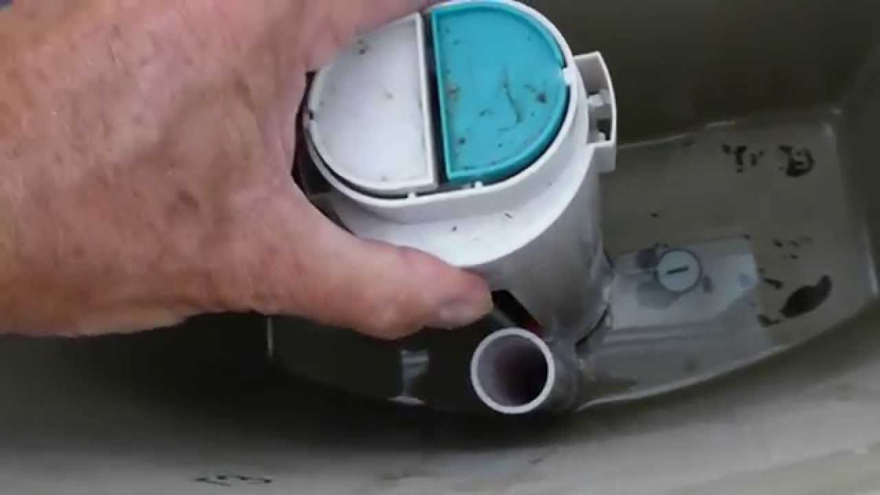
  • Flush Valve Seal/Diaphragm: A rubber seal at the bottom of the cistern that holds back the water. When lifted, it allows water to flow into the bowl.
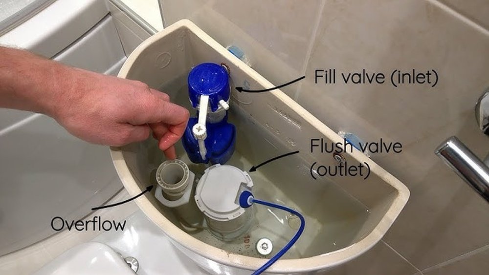
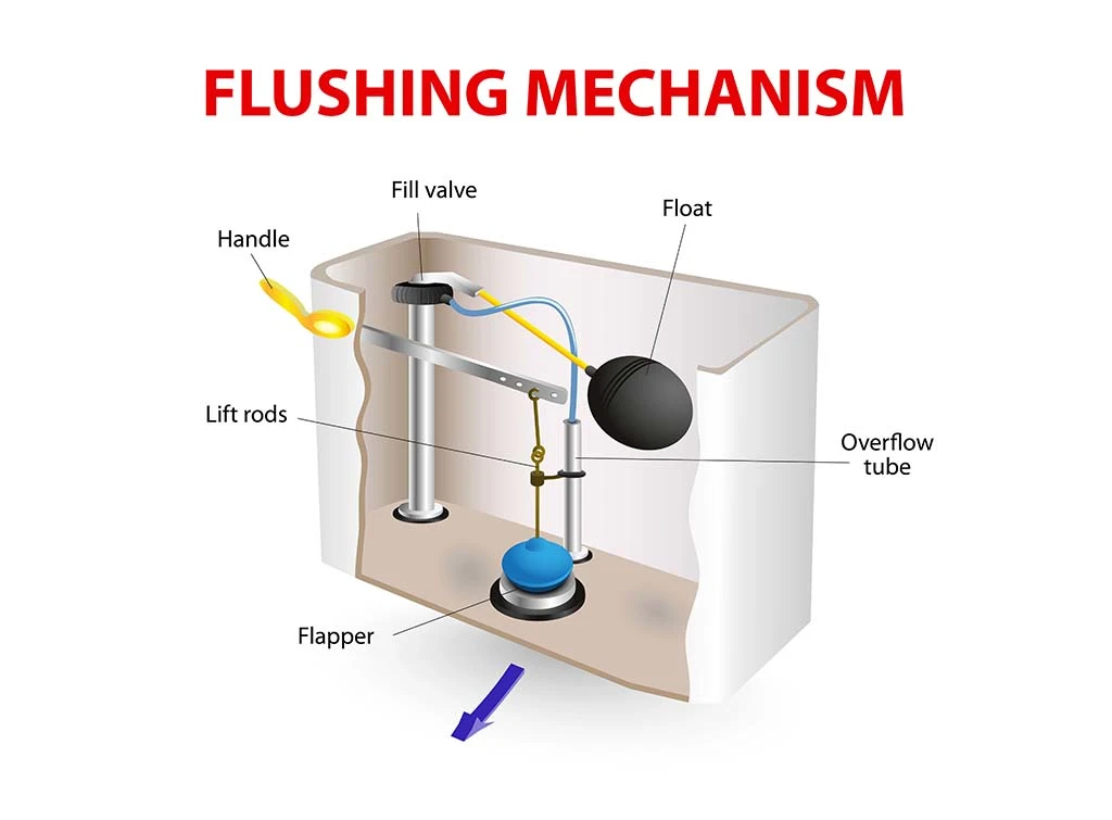
  • Overflow Pipe: A vertical pipe within the cistern that prevents water from exceeding a safe level.
  • Float Valve (Fill Valve): Controls the refilling of the cistern after a flush. While not directly related to the button, an improperly functioning fill valve can affect flush performance.

Troubleshooting A Non-responsive Push Button

The most common symptom is a button that feels loose, doesn’t depress, or doesn’t initiate a flush when pressed. This usually points to an issue with the button assembly or its direct linkage to the flush valve.

Button Feels Loose Or Wobbly

A loose button often indicates that the retaining nut holding the button assembly to the cistern lid is loose.

  • Remove the Cistern Lid: Carefully lift the ceramic lid off the cistern.
  • Locate the Nut: On the underside of the cistern lid, you’ll find the threaded housing for the push button. There’s usually a large plastic nut securing the entire assembly.
  • Tighten the Nut: Use your hand or pliers (with a cloth to prevent scratching) to tighten this nut. Be firm but avoid overtightening, which can crack the plastic or ceramic.
  • Test: Replace the lid and test the button.

Pro Tip: If the nut is difficult to grip or in a tight space, a basin wrench can be invaluable for reaching and tightening it.

Button Does Not Depress

If the button is stuck in the ‘out’ position and won’t move inward, several factors could be at play:

  • Obstruction: Debris, limescale, or even a dislodged internal component can jam the button.
  • Remove the cistern lid.
  • Examine the button mechanism. Gently try to wiggle it. If it feels stuck, look for any visible obstructions around the button’s housing.
  • If you see buildup, use a damp cloth or an old toothbrush to clean around the button. For stubborn limescale, a mild descaler might be necessary, but use it sparingly and rinse thoroughly.
  • Ensure the linkage rod or cable isn’t bent or caught.
  • Misaligned Mechanism: The button assembly might have shifted, causing it to bind.
  • Loosen the retaining nut slightly.
  • Reposition the button assembly so it moves freely.
  • Retighten the nut.
  • Internal Component Failure: The internal part of the button assembly that connects to the linkage might be broken. This often requires replacing the entire button assembly.

Button Depresses, But No Flush Occurs

This is a more complex issue, indicating that while the button is moving, the signal isn’t reaching or activating the flush valve.

  • Check Linkage:
  • Rod Systems: Ensure the rod connecting the button to the flush valve is still attached at both ends and is not bent. If it’s detached, reattach it. If it’s bent, try to straighten it carefully or replace it.
  • Cable Systems: Check that the cable is connected and taut. A slack cable won’t lift the flush valve sufficiently. Some cable systems have an adjustment screw near the button assembly or the flush valve.
  • Inspect Flush Valve: The problem might lie with the flush valve itself.
  • Stuck Flush Valve: The seal at the bottom of the flush valve might be stuck due to debris or wear.
  • Worn Seal: The rubber seal on the flush valve might be perished or damaged, preventing a proper seal when closed and thus a weak or no flush.
  • Incorrect Height: The flush valve might be sitting too low, meaning the button linkage isn’t lifting it high enough.
  • Water Level: An insufficient water level in the cistern means there isn’t enough water to create a strong flush. Check the water level marker inside the cistern. The water should typically reach about 1-2 cm below the overflow pipe. If it’s too low, the fill valve needs adjustment or repair.
Push Button Toilet Not Working

Credit: taekwondoluxembourg.com

Troubleshooting Weak Or Incomplete Flushes

A flush that barely empties the bowl or stops mid-cycle is frustrating and ineffective. This often relates to the volume of water released or the efficiency of the flush valve.

Insufficient Water In Cistern

As mentioned, a low water level is a primary cause of weak flushes.

  • Locate the Fill Valve: This is the mechanism that refills the cistern, usually with a float attached.
  • Adjust the Float: Most float valves have an adjustment screw or clip that allows you to set the water level.
  • Screw Adjustment: Turn the screw to raise or lower the float arm. Raising the float sets a higher water level.
  • Clip Adjustment: Some floats have clips that can be moved up or down the arm.
  • Check the Mark: Ensure the water level reaches the marked line inside the cistern (usually around 1-2 cm below the overflow pipe).
  • Test Flush: Flush the toilet and observe if the water level is now adequate.

Warning: Never set the water level above the top of the overflow pipe, as this will cause continuous water loss.

Flush Valve Not Lifting High Enough

Even with the correct water level, if the flush valve isn’t lifted sufficiently, the flush will be weak.

  • Adjust Linkage: If you have a rod system, the rod might need to be slightly longer or adjusted to lift the valve higher. If it’s a cable system, tighten the cable.
  • Flush Valve Height: Some flush valves can be adjusted vertically. Check your toilet’s manual for specific instructions.

Clogged Flush Valve Or Siphon Jet

The flush valve itself can become clogged with debris or mineral deposits, hindering water flow.

  • Isolate Water Supply: Turn off the water supply valve behind the toilet.
  • Flush Toilet: Press the button to empty the cistern as much as possible.
  • Access Flush Valve: Depending on your model, you may need to remove the flush valve assembly. This usually involves unscrewing a retaining nut at the bottom of the cistern from underneath.
  • Clean the Valve: Inspect the valve seal and the valve body for debris. Clean thoroughly with a brush and water. Use a descaler if necessary, but rinse extremely well.
  • Check Siphon Jet (Bowl): In the toilet bowl itself, at the bottom, there’s a small hole called the siphon jet. This hole injects water into the trapway to help start the siphonic action. If this hole is blocked with limescale, it can significantly weaken the flush. Use a small piece of wire or a stiff brush to clear it.

Worn Flush Valve Seal

The rubber seal at the base of the flush valve is critical. If it’s old, cracked, or deformed, it won’t seal properly when closed, leading to a slow leak into the bowl and a weak flush.

  • Inspect the Seal: With the cistern empty and the flush valve removed, examine the rubber seal.
  • Replace if Damaged: If the seal is worn, cracked, or brittle, it needs replacement. You can usually purchase a replacement seal specific to your flush valve model.
  • Installation: Fit the new seal securely onto the flush valve. Reassemble the flush valve and reconnect the water supply.
Push Button Toilet Not Working

Credit: www.indeepplumbing.com.au

Troubleshooting Dual-flush Button Issues

Dual-flush systems add complexity due to their two-button operation. Problems can arise with one button, both, or the mechanism that differentiates their function.

One Button Works, The Other Doesn’t

This typically points to an issue with the specific button or its corresponding linkage.

  • Stuck Button: If one button is stuck, follow the troubleshooting steps for a non-depressing button for that specific button.
  • Dislodged Linkage: The rod or cable connected to the non-working button might have detached. Open the cistern and check the connections.
  • Internal Mechanism Failure: Dual-flush button assemblies often have internal mechanisms that differentiate the two buttons. If one part of this mechanism breaks, one button will cease to function. This usually requires replacing the entire dual-flush button assembly.

Buttons Stuck Together Or Jammed

Sometimes, the two buttons can become misaligned or jammed, preventing either from operating correctly.

  • Remove Button Assembly: Carefully remove the entire dual-flush button assembly from the cistern lid.
  • Inspect: Look for any debris caught between the buttons or within their housing. Check if the internal plungers or levers are bent or misaligned.
  • Clean and Realign: Clean the assembly thoroughly. Gently try to straighten any bent parts. Ensure the buttons move freely within their housing before reinstalling.
  • Reinstall: Refit the assembly, ensuring it’s seated correctly before tightening the retaining nut.

Incorrect Flush Volume (dual-flush)

If both buttons seem to work but provide the wrong flush volume (e. g. , the ‘full’ flush is weak, or the ‘half’ flush is too strong), it suggests an issue with the flush valve or its adjustment.

  • Flush Valve Type: Most dual-flush systems use a specific type of flush valve designed to respond differently based on how long the button is pressed or which button is pressed.
  • Adjustment: Some flush valves have adjustable settings for the dual-flush function. Consult your toilet’s manual to see if your model is adjustable and how to set it correctly.
  • Faulty Flush Valve: The internal mechanism of the flush valve might be faulty, preventing it from performing the differentiated flushes correctly. This often requires replacing the entire flush valve.

Dealing With Concealed Cistern Push Plates

Concealed cisterns, where the workings are hidden behind a wall, present a different set of challenges. Accessing the components is more difficult, and troubleshooting often requires removing the push plate itself.

Accessing The Cistern Mechanism

The push plate is the primary interface. Removing it provides access to the flush actuator mechanism.

  • Identify Plate Type: Plates are usually attached with screws (often hidden under a cover) or a clip system. Some high-end plates are magnetically attached.
  • Remove Plate: Carefully follow the manufacturer’s instructions. This might involve pressing a release button, unscrewing visible or hidden screws, or gently prying the plate off.
  • Locate Actuator: Once the plate is off, you’ll see the flush actuator rods or pneumatic tubes connecting to the cistern.

Push Plate Not Activating Flush

If the plate feels loose or unresponsive:

  • Linkage Issues: The rods or cables connecting the plate to the flush valve might be disconnected, bent, or obstructed. Check their attachment points on both the plate mechanism and the flush valve.
  • Pneumatic System Faults: If your system uses air pressure (pneumatic), check for leaks in the tubing or issues with the air bellows.
  • Mechanical Faults: The internal levers or cams within the push plate mechanism might be broken or jammed.

Flush Valve Issues In Concealed Systems

Once the push plate is removed, you can inspect the flush valve. However, accessing the flush valve itself often requires removing an access panel in the wall or, in some cases, removing the entire cistern.

  • Standard Flush Valve Problems: Issues like worn seals, debris, or incorrect water levels are common, just as with exposed cisterns.
  • Professional Help: Due to the complexity of accessing concealed cisterns, it’s often advisable to call a plumber for anything beyond minor adjustments to the actuator rods.

When To Call A Professional Plumber

While many push-button toilet issues are DIY-friendly, there are times when professional expertise is essential.

  • Lack of Confidence or Tools: If you’re uncomfortable working with plumbing or lack the necessary tools, it’s safer to call a professional.
  • Concealed Cisterns: As mentioned, working on concealed cisterns can be complex and may require specialized knowledge and tools.
  • Persistent Problems: If you’ve tried basic troubleshooting steps and the problem persists, a plumber can diagnose more complex internal issues.
  • Cracked Cistern or Components: Any sign of cracks in the ceramic cistern or major plastic components necessitates professional assessment and likely replacement.
  • Water Damage Concerns: If you suspect a leak that could cause water damage to your property, immediate professional intervention is recommended.

A plumber can quickly identify faulty components, access difficult-to-reach areas, and ensure repairs are done correctly, preventing further damage or recurring issues. For instance, a common issue they encounter is a corroded or broken flush valve seat, which requires specific parts and expertise to replace correctly.

Maintenance Tips For Push-button Toilets

Regular maintenance can prevent many common problems and extend the life of your toilet’s flushing mechanism.

  • Regular Cleaning: Clean the cistern interior periodically (every 6-12 months) to remove limescale and debris. Use a mild cleaner and avoid abrasive materials.
  • Check Water Level: Periodically ensure the water level in the cistern is correct.
  • Button Check: Occasionally test both buttons (if dual-flush) to ensure they move freely.
  • Listen for Leaks: Pay attention to any constant trickling sounds from the cistern, which might indicate a worn flush valve seal.
  • Use Toilet Cleaners Wisely: Some harsh chemical toilet cleaners can degrade rubber seals over time. Opt for gentler cleaning methods.

Common Push Button Toilet Problems And Solutions

Here’s a quick reference table for common issues:

ProblemPossible Cause(s)Solution(s)
Button doesn’t depressObstruction, misalignment, broken internal partClean around button, tighten retaining nut, check/adjust linkage, replace button assembly.
Button loose/wobblyLoose retaining nutTighten retaining nut under cistern lid.
Button depresses, no flushDisconnected/bent linkage, faulty flush valve, low waterReconnect/straighten linkage, check/clean/replace flush valve seal, adjust water level via fill valve.
Weak or incomplete flushLow water level, flush valve not lifting high enoughAdjust fill valve float for higher water level, adjust linkage length, check/clean flush valve.
Dual-flush button not workingDislodged linkage, internal button mechanism faultCheck/reconnect linkage, clean button assembly, replace dual-flush button assembly.
Continuous running waterFaulty fill valve, worn flush valve sealAdjust/replace fill valve, replace flush valve seal.
Concealed cistern plate unresponsiveLinkage issue, pneumatic fault, mechanical faultRemove plate, check actuator rods/tubes, inspect for leaks, repair/replace plate mechanism or flush valve assembly (often requires plumber).

Frequently Asked Questions

How Often Should I Clean My Toilet Cistern?

It’s generally recommended to clean the inside of your toilet cistern every 6 to 12 months. This helps prevent the buildup of limescale, sediment, and other debris that can interfere with the flushing mechanism and affect performance. Use a mild cleaner and a soft brush, and ensure you rinse thoroughly afterwards.

Can I Adjust The Flush Strength On A Dual-flush Toilet?

Yes, most dual-flush toilets allow for adjustment of the flush strength, primarily by adjusting the water level in the cistern or the flush valve mechanism itself. Consult your toilet’s manual, as the method varies by manufacturer. Adjusting the float on the fill valve is a common way to set the overall water volume, which influences flush strength.

Some flush valves also have specific settings for dual-flush operation.

What Does It Mean If My Toilet Makes A Gurgling Sound After Flushing?

A gurgling sound after flushing can indicate a partial blockage in the drain line or the toilet trap. It suggests that air is being forced back through the trap as the water tries to drain. While not always an immediate emergency, it’s a sign that the toilet may not be flushing efficiently and could lead to a complete blockage if ignored.

Using a toilet plunger or a drain snake can often resolve minor blockages.

How Do I Know If I Need To Replace The Flush Valve?

You likely need to replace the flush valve if you experience persistent issues like a weak flush, the toilet constantly running (even after adjusting the fill valve), or if the flush valve seal is visibly worn, cracked, or deformed. If cleaning the flush valve and its seal doesn’t resolve the problem, replacement is usually the next step.

You can typically buy a replacement valve specific to your toilet model.

Is It Safe To Use Strong Chemical Cleaners Inside The Cistern?

While chemical cleaners can remove limescale, it’s advisable to use them sparingly, if at all, inside the cistern. Harsh chemicals can degrade the rubber seals and plastic components within the flushing mechanism over time, potentially leading to leaks and more significant problems.

Mild descalers or natural cleaning solutions like vinegar, followed by thorough rinsing, are often safer alternatives for routine maintenance.

A flush button that refuses to cooperate can be a perplexing issue, but by systematically working through the potential causes, from simple obstructions to worn internal components, most problems can be resolved. Understanding the mechanics of your specific toilet model is key.

For many, a loose nut, a bit of debris, or a misaligned rod will be the culprit, easily fixed with basic tools and a little patience. However, for more complex issues, especially those involving concealed cisterns or persistent problems, don’t hesitate to enlist the help of a qualified plumber.

Regular maintenance, including cleaning and checking water levels, will go a long way in ensuring your push-button toilet functions reliably for years to come.

Ceiling Crack Straight Line Meaning

A straight-line crack appearing on your ceiling can be a source of significant worry. These lines, often thin and precise, can range from seemingly minor cosmetic issues to indicators of more serious structural problems. Understanding the true meaning behind a straight ceiling crack is crucial for homeowners and property managers alike, as it dictates the necessary course of action, potential repair costs, and, most importantly, the safety of the building.

Many factors can contribute to ceiling cracks, from the natural settling of a house to more complex issues like water damage or foundation shifts. The appearance, location, and behavior of the crack provide vital clues. Is it hairline or wide?

Does it run across a beam or through a light fixture? Is it new, or has it been there for a while? These details help differentiate between a simple cosmetic flaw and a red flag demanding immediate attention from a qualified professional.

This article aims to demystify the various meanings of straight-line ceiling cracks, empowering you with the knowledge to assess the situation and make informed decisions about repair and maintenance.

Key Takeaways

  • Straight-line ceiling cracks are common and can stem from various causes, from minor settling to more significant structural concerns.
  • Crack characteristics (width, length, location, behavior) are key indicators of their underlying cause and severity.
  • Settling and drying are the most frequent culprits, often resulting in hairline cracks that are usually cosmetic.
  • Water damage can cause cracks, often accompanied by staining, sagging, and potential mold growth, requiring prompt repair of the leak and the ceiling.
  • Structural issues, such as foundation movement, excessive weight on the ceiling joists, or inadequate support, are serious and necessitate professional assessment.
  • Temperature fluctuations can cause materials to expand and contract, leading to cracks, especially in attics or uninsulated areas.
  • Proper diagnosis is essential, often requiring a professional inspection to determine the root cause and appropriate repair strategy.
  • Timely repairs prevent minor issues from escalating into costly structural problems and ensure occupant safety.
Ceiling Crack Straight Line Meaning

Credit: eppconcrete.com

Understanding The Anatomy Of A Ceiling Crack

Before delving into the specific meanings, it’s important to understand what constitutes a “straight-line” crack and what factors we analyze to interpret it. A straight-line crack on a ceiling typically refers to a fissure that runs in a relatively uniform direction, as opposed to spiderwebbing or random patterns. These lines can vary in length, from a few inches to spanning an entire room. Their width is also a critical determinant, ranging from barely visible hairline cracks to wider fissures that might allow light to pass through or even reveal the structure above.

The material of the ceiling also plays a role. Plaster and lath ceilings, common in older homes, tend to develop different types of cracks than modern drywall. Plaster can be more prone to cracking due to the drying and shrinking of the plaster itself, or due to the movement of the lath beneath it. Drywall, while more flexible, can crack at seams or around fasteners if not installed correctly or if subjected to significant stress. The location of the crack is another vital clue. Is it running parallel to a ceiling joist, across a beam, near a light fixture, or in the center of a large expanse? These positional details often point towards the forces acting upon the ceiling.

Finally, the behavior of the crack over time is paramount. Has it remained static since you noticed it? Has it widened? Has it reappeared after a repair? A crack that is actively growing or changing is a much stronger indicator of an ongoing problem than a static one. Observing these characteristics forms the foundation for diagnosing the cause of any straight-line ceiling crack.

Hairline Cracks: The Most Common Culprit

By far, the most frequent reason for a straight-line crack on a ceiling is the natural settling and drying of a house. Over time, especially in the first few years after construction, homes undergo minor shifts as the building materials dry out and settle into their final positions. Wood framing can shrink, and concrete foundations can compact slightly. These subtle movements put stress on the ceiling finishes, leading to small fissures.

These hairline cracks are typically very thin, often no wider than a credit card or even a strand of hair. They are usually found along seams in drywall or where different building materials meet, such as around trim or where drywall panels join. In older homes with plaster ceilings, these cracks can appear as the plaster shrinks or the lath beneath it moves. The good news is that these types of cracks are usually cosmetic. They don’t indicate a structural failure and are generally not a cause for alarm.

Cracks Related To Temperature And Humidity

Fluctuations in temperature and humidity can also cause building materials to expand and contract, leading to stress and subsequent cracking. This is particularly true for attics or rooms with significant temperature variations. Wood joists, drywall, and even paint can react to these changes. For instance, in the summer months, humidity can cause wood to swell, while in the winter, dry air can cause it to contract. This constant movement can eventually lead to straight-line cracks forming, often along joist lines or drywall seams.

Attic moisture is another factor. If an attic is not properly ventilated, moisture can accumulate, leading to condensation on the underside of the roof sheathing and the top of ceiling joists. This moisture can affect the integrity of the ceiling materials below over time. Similarly, a lack of insulation in certain areas can exacerbate temperature swings and their effects. These cracks are often more prevalent in colder climates or in homes with inadequate climate control and ventilation.

Ceiling Crack Straight Line Meaning

Credit: www.trinity-rose.co.uk

Water Damage: A More Serious Indicator

When a straight-line crack is accompanied by other tell-tale signs, it can point towards water damage, a more serious issue that needs prompt attention. Look for discoloration or staining around the crack. This is a strong indicator that water has seeped through the ceiling material. The stain might be brown, yellow, or even greenish, depending on the source of the water and the age of the stain.

Beyond staining, sagging of the ceiling material is another critical sign. Waterlogged drywall or plaster can become heavy and begin to droop, creating a visible bulge or dip that often runs along the line of the crack. In severe cases, the ceiling might feel soft or spongy to the touch. The source of the water could be a leaky roof, a faulty plumbing pipe in the floor above, condensation from an uninsulated HVAC duct, or even a problem with a bathroom or kitchen fixture on the level above.

Identifying The Source Of Water Intrusion

To effectively repair a crack caused by water damage, you must first identify and fix the source of the leak. This might involve:

  • Roof Inspection: Checking for damaged shingles, flashing issues around chimneys or vents, or ice dams.
  • Plumbing Check: Inspecting pipes in the floor above, especially around bathrooms, kitchens, and laundry areas, for leaks or condensation.
  • HVAC System: Examining ductwork for leaks or condensation, particularly if it runs through unconditioned spaces.
  • Appliance Leaks: Checking for issues with washing machines, dishwashers, or refrigerators on the floor above.

Once the leak is repaired, the damaged ceiling material will need to be replaced or repaired. Ignoring water damage can lead to more extensive problems, including mold growth, which poses significant health risks, and further structural deterioration.

Ceiling Crack Straight Line Meaning

Credit: eppconcrete.com

Structural Concerns: The Most Alarming Possibilities

While less common than settling or water damage, straight-line ceiling cracks can sometimes signal structural issues within the building. These are the most concerning types of cracks because they can compromise the integrity and safety of your home.

Foundation Movement

One of the most serious structural causes for ceiling cracks is foundation movement. If a home’s foundation shifts or settles unevenly, it can exert immense stress on the entire building structure, including the ceilings. This type of movement is often caused by:

  • Soil Expansion/Contraction: Changes in soil moisture content (e.g., due to drought or heavy rain) can cause the soil around the foundation to expand or contract, leading to pressure on the foundation walls.
  • Poor Soil Compaction: If the soil beneath the foundation was not adequately compacted during construction, it can settle over time.
  • Water Intrusion: Water pooling around the foundation can erode soil or exert hydrostatic pressure, causing movement.
  • Tree Roots: Large tree roots growing too close to the foundation can exert pressure.

Foundation movement often results in cracks that are wider, longer, and may appear in multiple locations throughout the house, not just on the ceiling. You might also notice sticking doors or windows, uneven floors, or cracks in walls that extend from the ceiling down. If you suspect foundation issues, it is imperative to contact a structural engineer or foundation repair specialist immediately.

Overloaded Ceiling Joists Or Beams

Another structural concern is when ceiling joists or beams are overloaded or inadequately supported. This can happen for several reasons:

  • Improper Renovations: Adding significant weight to the floor above without reinforcing the joists or beams. Examples include installing a heavy bathtub, a large tiled floor, or storing excessive weight in an attic space that was not designed for it.
  • Defective Materials: In rare cases, the original building materials might have been substandard or improperly installed.
  • Structural Modifications: Alterations to load-bearing walls or beams on the floor above can redistribute weight and stress the ceiling structure below.

When joists or beams are overloaded, they can deflect or sag under the weight. This deflection can pull on the ceiling material attached to them, causing straight-line cracks to appear, often running parallel to the affected joists. In severe cases, the sagging might be visible to the naked eye, and the crack could be quite wide. This situation requires assessment by a qualified contractor or structural engineer to determine the appropriate reinforcement or repair needed.

Issues With Support Structures

Cracks can also arise from problems with the primary support structures of the ceiling itself. This could include issues with:

  • Wall Cracks: If the walls supporting the ceiling joists develop cracks, this can lead to movement and stress on the ceiling.
  • Bearing Points: Problems at the points where joists rest on walls or beams can cause instability.
  • Joist Hangers and Fasteners: If these are damaged, corroded, or improperly installed, they can lead to sagging and cracking.

These issues often manifest as cracks that appear near the edges of the ceiling or where ceiling joists meet supporting walls. Again, any suspicion of compromised structural support warrants immediate professional evaluation.

Installation And Material-related Cracks

Sometimes, straight-line cracks are not due to environmental factors or structural shifts but rather issues with the initial installation or the materials used.

Drywall Seam Cracks

In homes with drywall ceilings, the most common installation-related cracks occur along the seams where two drywall panels meet. These seams are typically covered with joint tape and compound (mud). If the tape is not applied correctly, if too much or too little compound is used, or if the drywall is not properly supported by framing, cracks can form along these seams.

These cracks often appear as fine, straight lines. They can be exacerbated by minor house settling or temperature fluctuations. While often cosmetic, if the joint tape is severely compromised, the crack might widen and require re-taping and mudding. A common issue is when the tape is embedded too deeply, leaving a noticeable indentation that eventually cracks.

Plaster And Lath Issues

Older homes often feature plaster and lath ceilings. Plaster is applied over thin strips of wood called lath. Over time, the lath can shrink, warp, or loosen, causing the plaster to crack. The plaster itself can also dry out and become brittle, leading to fissures.

Straight-line cracks in plaster ceilings can run along the lines of the lath or occur in larger sections where the plaster has lost adhesion. These cracks can sometimes be quite extensive and may require significant repair, potentially involving removing damaged plaster and reapplying new layers, or even replacing sections of lath.

Poor Finishing Techniques

Even with sound materials and structural integrity, poor finishing techniques can lead to cracks. This includes:

  • Inadequate Priming: Not priming drywall before applying compound can lead to uneven drying and increased stress.
  • Rushing the Process: Applying multiple layers of joint compound too quickly without allowing adequate drying time between coats can trap moisture and cause shrinkage issues.
  • Over-sanding: Excessive sanding can weaken the joint compound and tape.

These subtle errors in the finishing process can create weaknesses that eventually manifest as straight-line cracks, even if the underlying structure is sound.

Comparison Of Ceiling Crack Causes

To better illustrate the differences between common causes of straight-line ceiling cracks, consider the following comparative table. This highlights key distinguishing features that can help in initial assessment.

Characteristic Settling/Drying Water Damage Structural Issues Installation/Material
Crack Appearance Hairline, fine, often along seams Can be varied, often with staining/sagging Wider, longer, may be in multiple locations, accompanied by other signs Fine, along drywall seams or plaster lines
Associated Signs Usually none, or very minor cosmetic issues Staining, sagging, dampness, potential mold Sticking doors/windows, uneven floors, wall cracks, visible deflection None, or minor imperfections in finish
Severity Low (cosmetic) Moderate to High (requires leak repair) High to Very High (potential safety hazard) Low to Moderate (cosmetic or repairable)
Typical Location Drywall seams, corners, ceiling-wall junctions Areas directly below plumbing, roof leaks, or condensation points Throughout the house, especially where load-bearing elements are stressed Drywall seams, plaster lines, corners
DIY Repair Potential High (for minor hairline cracks) Low (requires leak source identification first) Very Low (requires professional assessment) Moderate (for minor seam repairs)

This table provides a quick reference, but it’s essential to remember that symptoms can sometimes overlap, making professional diagnosis crucial.

When To Call A Professional

While some minor hairline cracks can be addressed with DIY repairs, there are several scenarios where calling a professional is not just recommended but essential for safety and long-term building health.

Immediate Red Flags

Certain signs warrant an immediate call to a qualified professional, such as a structural engineer or a licensed building contractor:

  • Wide Cracks: Cracks wider than 1/4 inch (about 6mm) often indicate significant stress.
  • Deep Cracks: Cracks that appear to go through the entire thickness of the ceiling material.
  • Active Movement: Cracks that are visibly widening or changing over a short period.
  • Sagging Ceiling: Any noticeable drooping or bowing of the ceiling.
  • Water Intrusion: Persistent dampness, active leaks, or extensive staining.
  • Associated Structural Signs: Sticking doors/windows, uneven floors, or cracks in walls and foundations.
  • Previous Repairs Failing: If a crack reappears after a previous repair attempt.

Types Of Professionals To Consider

Depending on the suspected cause, you might need to consult different specialists:

  • General Contractor: For general repairs, water damage remediation, and installation-related issues.
  • Plumber: If the crack is suspected to be related to plumbing leaks.
  • Roofer: If the water damage appears to originate from the roof.
  • Structural Engineer: For any concerns about foundation movement, overloaded joists, or significant structural integrity issues. This is often the most critical professional to consult for serious structural cracks.
  • Foundation Repair Specialist: If foundation issues are strongly suspected.

In my experience, trying to patch a crack caused by a serious underlying issue without addressing the root cause is a futile effort that wastes time and money and can mask a dangerous problem. Always prioritize identifying and rectifying the source of the crack before cosmetic repairs.

Repairing Straight-line Ceiling Cracks

The repair process for a straight-line ceiling crack depends entirely on its cause.

Cosmetic Repairs For Minor Cracks

For simple hairline cracks resulting from settling or minor drying, cosmetic repairs are usually sufficient. This typically involves:

  • Cleaning: Gently clean the area around the crack to remove dust and debris.
  • Sanding (Optional): Lightly sand the crack to create a smoother surface.
  • Filling: Apply a spackling compound or joint compound to fill the crack. For hairline cracks, a lightweight spackle might suffice. For slightly wider cracks, you may need to use a joint compound and possibly embed paper or fiberglass tape over the crack to reinforce it, especially if it runs along a drywall seam.
  • Sanding: Once the compound is dry, sand it smooth.
  • Priming and Painting: Apply a primer to the repaired area and then paint to match the existing ceiling color.

For plaster ceilings, specialized plaster repair compounds may be necessary.

Repairing Water-damaged Ceilings

If water damage is the cause, the repair is multi-step:

  • Fix the Leak: This is the absolute first and most critical step. Until the water source is stopped, any repair will be temporary.
  • Dry the Area: Ensure the affected area is completely dry. This may involve using fans or dehumidifiers.
  • Assess Damage: Remove any severely damaged or moldy material. If the drywall is significantly warped or stained, it will likely need to be replaced.
  • Repair/Replace: Patch or replace the damaged sections of the ceiling. This might involve cutting out a section of drywall and installing a new piece, then taping, mudding, and finishing the seams.
  • Prime and Paint: Apply a stain-blocking primer to cover any residual discoloration, followed by your ceiling paint.

Structural Repairs

Structural repairs are complex and always require professional intervention. The specific repair will depend on the diagnosed issue:

  • Foundation Repair: May involve underpinning, crack injection, or drainage system installation.
  • Reinforcing Joists/Beams: Might include sistering joists (adding new beams alongside existing ones), installing additional supports, or upgrading beam sizes.
  • Addressing Support Issues: Involves repairing or reinforcing walls, bearing points, or fasteners as identified by the engineer.

These repairs are significant undertakings and should only be performed by experienced professionals following the recommendations of a structural engineer.

Pro Tip:

When dealing with any ceiling crack, especially if you’re unsure of the cause, it’s always better to err on the side of caution. A small upfront investment in a professional inspection can save you from much larger, more expensive, and potentially dangerous problems down the line.

Frequently Asked Questions

What Is The Difference Between A Ceiling Crack And A Wall Crack?

While both can indicate similar underlying issues like settling or structural stress, their location and implications can differ. Ceiling cracks directly affect the overhead surface, and their presence might suggest issues with the floor structure above, roof, or ceiling joists.

Wall cracks can indicate foundation problems, lateral pressure on walls, or issues with framing. However, significant foundation movement often causes cracks in both walls and ceilings simultaneously, appearing in stair-step or diagonal patterns on walls and straight or spiderweb patterns on ceilings.

How Often Should I Inspect My Ceiling For Cracks?

Regular visual inspections are recommended, especially during seasonal changes when temperature and humidity fluctuations are most significant. A thorough check every six months, or after major weather events, can help catch new cracks or changes in existing ones early. Pay close attention to areas prone to water leaks, such as bathrooms, kitchens, and areas directly beneath the roof.

Can A Ceiling Crack Mean My House Is About To Collapse?

This is a highly unlikely scenario for most straight-line cracks. While some structural cracks can be serious, a house collapsing due to a ceiling crack is extremely rare and typically involves catastrophic failure of multiple load-bearing elements. Most ceiling cracks are due to minor settling, material stress, or water damage, which are repairable and do not pose an immediate collapse risk.

However, signs like significant sagging, very wide cracks, or cracks accompanied by falling debris should be treated with urgency and evaluated by a professional immediately.

Is It Safe To Paint Over A Ceiling Crack?

Painting over a hairline crack caused by minor settling or drying is generally safe and can be a cosmetic fix. However, if the crack is due to water damage, structural issues, or is actively growing, painting over it will not solve the underlying problem and may even mask warning signs.

It’s crucial to diagnose the cause before applying any cosmetic treatment. If there’s any doubt, it’s best to investigate further or consult a professional.

What Are The Long-term Consequences Of Ignoring A Ceiling Crack?

Ignoring a ceiling crack can lead to several long-term consequences, depending on its cause. Minor cosmetic cracks might simply worsen in appearance over time. Cracks from water damage can lead to mold growth, rot in the ceiling structure, and further damage to insulation and finishes, potentially affecting indoor air quality and structural integrity.

Cracks from structural issues, if left unaddressed, can compromise the overall safety and stability of the building, leading to more extensive and costly repairs in the future. Early detection and repair are always the most cost-effective

Ryobi Pressure Washer Soap Not Working

Ryobi Pressure Washer Soap Not Working

The hum of a pressure washer is a familiar sound for homeowners tackling spring cleaning or preparing for summer gatherings. Ryobi, a popular brand known for its accessible and reliable tools, offers a range of pressure washers that make these tasks more manageable.

However, a common frustration arises when the pressure washer’s soap dispenser or detergent system fails to work as expected. Instead of a powerful stream of soapy water to loosen grime, you get only plain water, significantly diminishing the cleaning power.

This issue can stem from various causes, from simple blockages to more complex mechanical problems within the pressure washer itself or the detergent you’re using.

Understanding why your Ryobi pressure washer isn’t dispensing soap is crucial for getting back to effective cleaning. This problem isn’t unique to Ryobi; many pressure washer brands can experience similar issues. The good news is that most of these problems are fixable with a bit of troubleshooting and basic maintenance.

This article will guide you through the most common reasons why your Ryobi pressure washer’s soap function might not be working, offering practical solutions to get your machine back to its full cleaning potential. We’ll cover everything from checking your detergent and siphon tube to inspecting the unloader valve and ensuring proper assembly.

Key Takeaways

  • Clogged Siphon Tube: The most frequent culprit is a blockage in the detergent siphon tube, preventing soap from reaching the pump.
  • Incorrect Detergent: Using the wrong type or viscosity of detergent can hinder its ability to be drawn into the system.
  • Low Water Pressure: Insufficient incoming water pressure can prevent the soap nozzle or siphon system from engaging correctly.
  • Faulty Detergent Filter/Strainer: A clogged filter in the siphon tube prevents detergent flow.
  • Unloader Valve Issues: Problems with the unloader valve can affect overall pressure and the soap dispensing mechanism.
  • Assembly Errors: Incorrectly attached soap nozzles or hoses can disrupt the system.
  • Maintenance is Key: Regular cleaning of the siphon tube and filter is essential to prevent future issues.
Ryobi Pressure Washer Soap Not Working

Credit: www.youtube.com

Understanding Your Ryobi Pressure Washer’s Soap System

Ryobi pressure washers, like most on the market, typically employ a simple yet effective system for dispensing detergent. The core principle relies on venturi action, a phenomenon where a fluid moving at high speed through a constricted section of a pipe creates a pressure drop, drawing in a secondary fluid. In your pressure washer, the high-pressure water stream passing through a specific part of the pump or a dedicated nozzle creates this vacuum effect. This vacuum then pulls the detergent from its reservoir up through a siphon tube and mixes it with the water before it’s expelled through the low-pressure soap nozzle.

There are generally two main types of detergent systems you’ll find on Ryobi pressure washers:

Internal Siphon Tube System

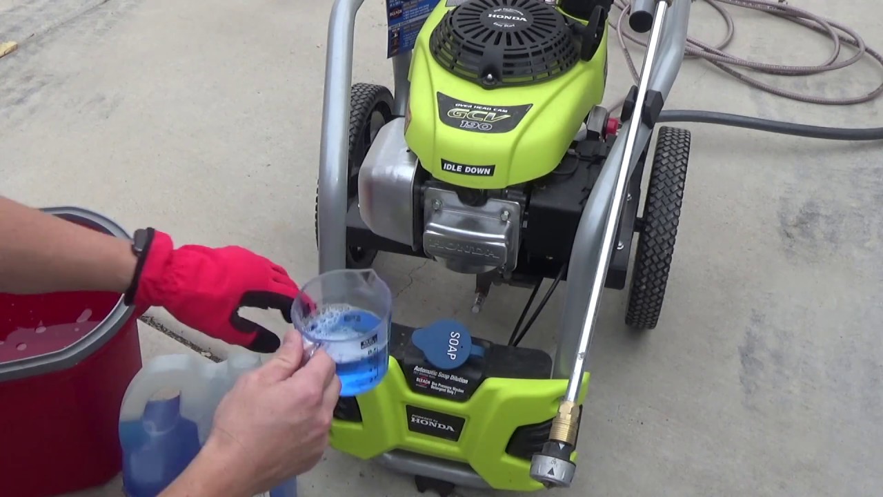
Many electric and some smaller gas-powered Ryobi pressure washers utilize an internal siphon tube. This system involves a small plastic or rubber tube that is submerged in your detergent container. The other end of the tube connects to a port on the pressure washer unit, often near the water inlet or pump housing.

When the machine is running and set to the appropriate soap-dispensing mode (usually indicated by a specific nozzle or a setting on the machine), the water flow creates suction at the connection point, drawing the detergent up the tube and into the water stream.

Detergent Tank Or Reservoir

Some Ryobi models, particularly those with a higher GPM (gallons per minute) rating, might feature an integrated detergent tank. In this setup, the detergent is stored directly within the pressure washer unit. A pump or a dedicated internal mechanism then draws the detergent from this tank and mixes it with the water.

While convenient, these tanks can also be prone to clogging if not cleaned regularly.

Soap Nozzles And Settings

The method for activating the soap dispenser varies. Some models require you to switch out the high-pressure cleaning nozzle for a specific low-pressure soap nozzle. This nozzle is designed with a larger orifice, reducing the water pressure and allowing the venturi system to effectively draw in detergent. Other Ryobi models might have a dial or a button that adjusts the machine’s settings to engage the soap dispenser. Always consult your Ryobi pressure washer’s user manual for the specific instructions related to your model. Misunderstanding this step is a common reason for the soap not working.

Ryobi Pressure Washer Soap Not Working

Credit: www.youtube.com

Common Reasons For Ryobi Pressure Washer Soap Not Working

When your Ryobi pressure washer fails to dispense soap, it’s usually due to one or a combination of straightforward issues. Identifying the root cause is the first step toward a swift resolution.

Blocked Or Clogged Siphon Tube

This is by far the most common reason for a Ryobi pressure washer not dispensing soap. Detergent, especially if it dries out or if sediment is present, can harden and create a blockage within the thin siphon tube. This obstruction prevents the detergent from being drawn up into the water stream.

  • Cause: Dried detergent residue, dirt, or debris in the detergent container or the tube itself.
  • Symptom: Water sprays out at normal pressure, but no soap is visible.
  • Fix: Disconnect the siphon tube from the pressure washer. Inspect the tube for blockages. You can often clear minor clogs by using a thin, flexible wire (like a straightened paperclip, being careful not to puncture the tube) or by flushing it with warm water. For persistent clogs, soaking the tube in warm, soapy water or a mild degreaser might be necessary. Ensure the tube is completely dry before reattaching.

Clogged Detergent Filter/strainer

Most Ryobi pressure washers with a siphon tube system have a small filter or strainer at the end of the tube that sits in the detergent. This filter is designed to prevent larger particles from entering the tube and clogging the system. Over time, this filter can become clogged with detergent residue or debris.

  • Cause: Accumulation of detergent residue, dirt, or sediment on the filter mesh.
  • Symptom: Similar to a blocked siphon tube, but the blockage is specifically at the intake point.
  • Fix: Gently pull the filter off the end of the siphon tube. Clean it thoroughly under running water. A small brush, like an old toothbrush, can help dislodge stubborn residue. If the filter is damaged or excessively clogged, it may need to be replaced. Replacement filters are usually inexpensive and available from Ryobi or third-party suppliers.

Incorrect Detergent Type Or Viscosity

Not all soaps are created equal, especially when it comes to pressure washers. Using the wrong type of detergent can significantly impact its ability to be dispensed.

  • Cause: Using household detergents (like dish soap), soaps that are too thick, or soaps not specifically formulated for pressure washers. These can clog the system or fail to be drawn up effectively.
  • Symptom: Detergent flows inconsistently, or not at all. The water might look slightly foamy but lacks the expected cleaning concentration.
  • Fix: Always use pressure washer-specific detergents. These are formulated with the correct viscosity and chemical properties to work with the venturi system. Avoid using car wash soaps or general-purpose cleaners unless they explicitly state they are safe and effective for pressure washers. If you suspect your current detergent is too thick, try diluting it slightly with water, but always follow the detergent manufacturer’s recommendations.

Low Incoming Water Pressure

Pressure washers rely on a certain level of water supply pressure to operate correctly, including engaging the detergent siphon. If your water source pressure is too low, the venturi effect might not be strong enough to draw the detergent.

  • Cause: Using a hose that is too narrow, too long, or kinked. The main water valve at your house is not fully open. The municipal water pressure is low.
  • Symptom: The pressure washer may not generate full pressure, and the soap system fails to engage.
  • Fix: Ensure you are using a garden hose of at least 5/8 inch diameter and no longer than 50 feet. Check for kinks or restrictions in the hose. Make sure the main water supply valve is fully open. You can test your home’s water pressure using a pressure gauge that screws onto an outdoor faucet. Ryobi typically recommends a minimum of 40 PSI (pounds per square inch) of water supply pressure.

Incorrect Nozzle Or Setting

As mentioned earlier, many Ryobi pressure washers require a specific nozzle or setting for soap dispensing. Using the wrong one will prevent the system from working.

  • Cause: Using the high-pressure nozzle instead of the dedicated soap nozzle, or failing to select the correct setting on models with a dial.
  • Symptom: High-pressure water stream, but no soap.
  • Fix: Consult your Ryobi pressure washer’s manual to identify the correct soap nozzle (often black and with a wider orifice) or the correct setting on the machine. Ensure the nozzle is securely attached. If you’ve lost the soap nozzle, you’ll need to purchase a replacement.

Air In The Detergent Line

If you’ve recently refilled your detergent or reconnected the siphon tube, there might be air trapped in the line. This air pocket can prevent the detergent from being drawn up.

  • Cause: Air introduced into the siphon tube system during refilling or reassembly.
  • Symptom: Intermittent or no soap dispensing until the air is purged.
  • Fix: After ensuring the siphon tube is submerged in detergent, run the pressure washer on the soap setting for a minute or two. This should push any trapped air out of the line. You may need to reposition the siphon tube slightly in the detergent to help prime the system.

Issues With The Unloader Valve

The unloader valve is a critical component that regulates water pressure. While less common, a malfunctioning unloader valve can sometimes affect the pressure dynamics in a way that impedes the detergent system.

  • Cause: A faulty unloader valve that isn’t regulating pressure correctly.
  • Symptom: Inconsistent pressure, overheating, or failure of the detergent system. This is often accompanied by other pressure-related issues.
  • Fix: Troubleshooting the unloader valve is more complex and may require professional assistance. If you suspect this is the issue, especially if you’re experiencing other pressure problems, it’s best to consult your Ryobi manual or contact Ryobi customer support.
Ryobi Pressure Washer Soap Not Working

Credit: www.youtube.com

Troubleshooting Steps For A Ryobi Pressure Washer Soap Dispenser

When faced with a Ryobi pressure washer that’s not dispensing soap, a systematic approach to troubleshooting will save you time and frustration. Follow these steps in order:

Step 1: Verify The Basics

Before diving into more complex issues, confirm the simple things:

  • Correct Nozzle/Setting: Ensure you are using the low-pressure soap nozzle or the designated soap setting on your Ryobi pressure washer. If you’re unsure, check your owner’s manual.
  • Siphon Tube Submerged: Confirm the end of the detergent siphon tube is fully submerged in the detergent. If it’s not, the pump won’t be able to draw it up.
  • Detergent Level: Make sure there is sufficient detergent in your container. An empty container is an obvious, yet sometimes overlooked, reason for no soap.
  • Water Supply: Double-check that your garden hose is fully connected to the pressure washer and the water source, and that the water supply is turned on fully.

Step 2: Inspect The Detergent Siphon System

This is where most soap-related problems lie.

  • Disconnect Siphon Tube: Carefully detach the detergent siphon tube from the pressure washer unit.
  • Check for Blockages: Visually inspect the tube for any visible obstructions. If you see any, try to remove them.
  • Clean the Detergent Filter: At the end of the siphon tube that goes into the detergent, there’s usually a small filter or strainer. Remove this filter and clean it thoroughly under running water. Use a small brush if necessary.
  • Flush the Tube: If the tube still seems blocked or you want to be thorough, try flushing it with warm water. You can do this by connecting a garden hose to the end that attaches to the pressure washer and running water through it, or by submerging the intake end in warm water and allowing the machine to draw it up (if possible, on a soap setting).

Step 3: Test With Different Detergent

The type of detergent can be a critical factor.

  • Use Pressure Washer Detergent: Ensure you are using a detergent specifically designed for pressure washers.
  • Try a Different Brand/Type: If you’re using a pressure washer detergent, try a different brand or formulation. Some detergents have different viscosities that might work better with your specific Ryobi model.
  • Dilute if Necessary: If your detergent seems unusually thick, try diluting it slightly with water according to the manufacturer’s instructions.

Step 4: Check Water Inlet And Hose

A weak water supply can cripple the soap system.

  • Inspect Inlet Screen: Ensure the water inlet screen on the pressure washer itself is clean and free of debris. A clogged inlet screen restricts water flow.
  • Hose Condition: Verify that your garden hose is not kinked, damaged, or excessively long. Use a hose of at least 5/8-inch diameter.
  • Water Pressure Test: If possible, test your home’s water pressure at the spigot where you connect the hose. It should ideally be at least 40 PSI.

Step 5: Examine The Detergent Reservoir/tank

If your Ryobi has an integrated detergent tank, inspect it.

  • Clean the Tank: Empty the tank and clean it thoroughly. Dried detergent can leave a residue that hardens and blocks the internal lines.
  • Check Internal Lines: Look for any visible blockages within the tank or where the internal lines connect.

Step 6: Consider The Pump And Unloader Valve

If all the above steps fail, the issue might be more internal.

  • Listen to the Pump: Does the pump sound normal? Any unusual noises could indicate a more serious problem.
  • Unloader Valve: While difficult to diagnose without specialized knowledge, a malfunctioning unloader valve can affect pressure and detergent flow. If you suspect this, consult your manual or seek professional help.

Pro Tip: After performing any cleaning or maintenance on the siphon tube or filter, it’s a good practice to run the pressure washer with plain water for a few minutes to flush out any loosened debris before attempting to use detergent again.

Maintaining Your Ryobi Pressure Washer For Optimal Soap Performance

Preventing issues with your Ryobi pressure washer’s soap dispenser is far easier than fixing them. Regular maintenance is the key to ensuring it works reliably whenever you need it. By incorporating a few simple habits into your cleaning routine, you can significantly extend the life of your machine and avoid frustrating downtime.

Post-use Cleaning Routine

The most critical time for maintenance is immediately after you finish using your pressure washer, especially if you used detergent.

  • Flush the Detergent System: After you’ve finished cleaning, disconnect the siphon tube from the detergent bottle. Then, place the siphon tube into a bucket of clean water and run the pressure washer on the soap setting for about 1-2 minutes. This process flushes out any remaining detergent from the siphon tube, filter, and internal passages, preventing it from drying and hardening.
  • Clean the Detergent Filter: Remove the detergent filter from the end of the siphon tube and rinse it under clean running water. Ensure all detergent residue is removed. Store the filter attached to the tube or in a clean, dry place.
  • Empty Detergent Container: If you didn’t use all the detergent, consider emptying the bottle and rinsing it. This prevents dried residue from forming in the container, which can then contaminate the siphon tube the next time you use it.

Regular Inspections

Beyond the immediate post-use cleaning, periodic checks will catch potential problems early.

  • Inspect Siphon Tube: Regularly check the siphon tube for any signs of cracking, kinking, or hardening. A compromised tube can lead to leaks or prevent proper suction. Replace the tube if it shows significant wear.
  • Check Water Inlet Screen: Before each use, ensure the water inlet screen on the pressure washer is clean and free of debris. A clogged screen restricts water flow, which can impact both pressure and the soap dispensing function.
  • Examine Nozzles: Ensure all your pressure washer nozzles are clean and free from debris. Blockages in the soap nozzle can also affect performance.

Proper Detergent Storage

How you store your detergent can also prevent future issues.

  • Seal Tightly: Always ensure the detergent bottle cap is sealed tightly after use.
  • Store Upright: Store detergent bottles upright in a cool, dry place away from direct sunlight. This helps prevent leakage and premature degradation of the chemicals.

Seasonal Maintenance

For pressure washers that are stored for extended periods (e. g. , during winter months), specific maintenance is crucial.

  • Run Clean Water: Before storing, run clean water through the detergent system as described in the post-use cleaning routine.
  • Use Pump Saver: If you live in a region with freezing temperatures, use a pump saver fluid to protect the pump from damage caused by water freezing and expanding. Follow the product instructions carefully. While pump saver primarily protects the pump, ensuring all detergent residue is out first is good practice.

By adopting these maintenance habits, you’ll significantly reduce the likelihood of encountering a non-working soap dispenser on your Ryobi pressure washer, ensuring it’s always ready for your cleaning tasks.

Comparing Ryobi Pressure Washer Detergent Systems

While the core principle of detergent dispensing remains similar across many Ryobi models, there can be variations in the specific implementation. Understanding these differences can help you diagnose issues more effectively. Here’s a look at common system types and their associated considerations:

FeatureInternal Siphon Tube SystemIntegrated Detergent Tank System
**Detergent Storage**External bottleBuilt-in tank on the pressure washer
**Mechanism**Venturi suction via siphon tubeInternal pump or dedicated suction line from tank
**Capacity**Limited by external bottle sizeLimited by internal tank size
**Cleaning Ease**Easy to clean siphon tube and filterRequires cleaning the entire internal tank and lines
**Common Issues**Clogged siphon tube/filter, incorrect detergent viscosityClogged tank/lines, detergent drying inside tank
**Typical Models**Most electric models, some smaller gas modelsSome mid-range to higher-end gas models
**Maintenance Focus**Cleaning siphon tube and external filterThoroughly cleaning the internal tank and associated lines

Case Study: The Persistent Clog

Sarah, a homeowner, recently purchased a Ryobi electric pressure washer and was excited to tackle her grimy patio. After setting everything up, she connected the detergent bottle via the siphon tube and selected the soap nozzle. To her dismay, only water came out.

She repeated the process, ensuring the tube was submerged, but the result was the same. Frustrated, she checked online forums and found numerous mentions of clogged siphon tubes.

Following advice, Sarah disconnected the siphon tube. She found the small filter at the end was coated in a thick, white residue. She meticulously cleaned the filter under hot water and used a straightened paperclip to gently probe the siphon tube, dislodging a small, dried clump of detergent.

After reassembling everything and running the machine with plain water for a minute to flush any loose debris, she tried the detergent again. This time, a rich stream of soapy water emerged, quickly cutting through the patio grime. Sarah learned the importance of regular flushing and cleaning the detergent filter, especially after the first use when detergent might be more prone to residue.

Advanced Troubleshooting And When To Seek Help

If you’ve gone through the basic and intermediate troubleshooting steps and your Ryobi pressure washer still isn’t dispensing soap, it’s time to consider more complex issues or professional assistance. While many problems are user-fixable, some require specialized knowledge or tools.

Checking The Water Inlet Screen

The water inlet screen on the pressure washer itself is a crucial filter that prevents debris from entering the pump. If this screen is clogged, it restricts water flow, which can indirectly affect the detergent system’s ability to draw soap via venturi action.

  • Location: Typically found where you connect your garden hose to the pressure washer.
  • Inspection: Unscrew the hose connection. You’ll see a small, often brass or plastic, screen. Carefully remove it (a pair of needle-nose pliers might be helpful) and inspect it for dirt, sand, or mineral deposits.
  • Cleaning: Rinse the screen thoroughly under running water. Use a soft brush to gently scrub away any stubborn debris. Ensure it’s completely clean before reinserting it.
  • Reassembly: Once clean, carefully place the screen back into its housing and reattach the garden hose.

Understanding The Unloader Valve’s Role

The unloader valve is a vital safety and operational component. Its primary function is to divert water flow back into the pump’s bypass loop when the trigger gun is released, preventing pressure buildup that could damage the system. However, its operation is intrinsically linked to the overall water pressure dynamics within the pump.

  • How it Affects Soap: If the unloader valve is sticking, partially blocked, or malfunctioning, it can lead to inconsistent water pressure. This inconsistency might prevent the venturi system from creating a strong enough vacuum to draw detergent effectively. Symptoms of an unloader valve issue can include fluctuating pressure, the pump not reaching full pressure, or the pump running hot.

*

Whirlpool Microwave Door Error

Whirlpool Microwave Door Error

A Whirlpool microwave door error can be a frustrating and disruptive issue, leaving you unable to use a vital kitchen appliance. Whether it’s a persistent error code, a door that won’t latch properly, or a microwave that refuses to start due to a perceived door malfunction, these problems can halt your meal preparation in its tracks. Understanding the common causes, troubleshooting steps, and potential solutions for these errors is crucial for restoring your Whirlpool microwave to full functionality efficiently and safely.

This comprehensive guide will navigate you through the intricacies of Whirlpool microwave door errors. We’ll explore the underlying reasons for these malfunctions, provide step-by-step diagnostic procedures, and outline the repair or replacement options available. Our aim is to empower you with the knowledge to tackle these issues, whether you’re a seasoned DIYer or simply seeking to understand what might be wrong before calling a professional.

Key Takeaways

  • Door Latch Issues: The most frequent cause of Whirlpool microwave door errors is a faulty door latch mechanism, including broken latches, misaligned doors, or obstructed sensors.
  • Safety Interlocks: Microwaves have multiple safety interlock switches that prevent operation when the door is open. If these switches fail or are not triggered correctly, an error can occur.
  • Control Panel/Board Problems: Less commonly, errors can stem from issues with the microwave’s electronic control panel or main control board.
  • Troubleshooting Steps: Basic troubleshooting includes unplugging the microwave, checking for obstructions, and verifying the door closes securely.
  • Error Codes: Specific error codes on Whirlpool microwaves can provide clues to the problem, though they often require consulting the user manual or a technician.
  • Professional Repair vs. DIY: Simple fixes like clearing obstructions can be DIY, but complex electrical issues or component replacements often necessitate professional service.
  • Preventative Maintenance: Keeping the door and latch area clean and ensuring the microwave is level can help prevent future door-related errors.

Understanding Whirlpool Microwave Door Error Codes

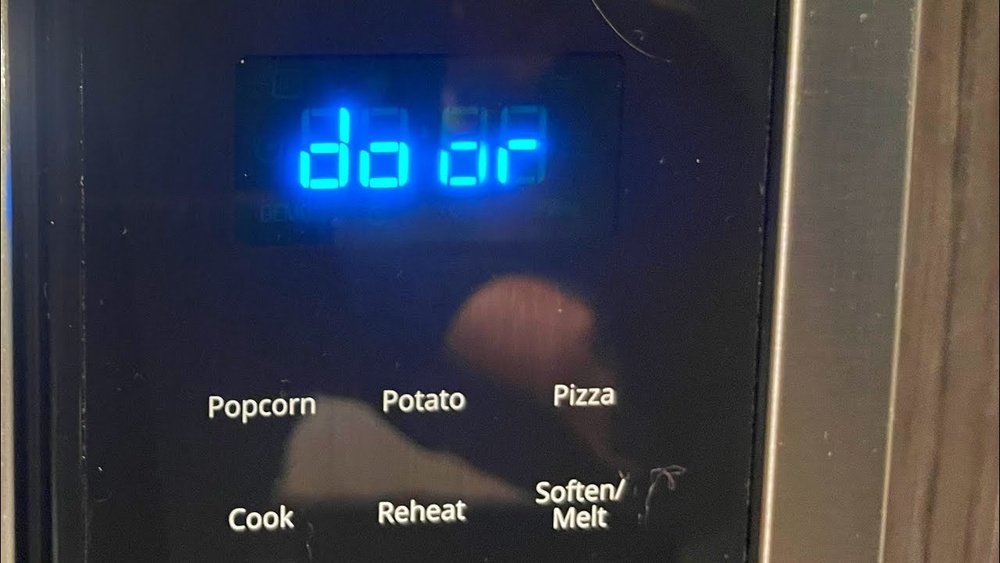
Whirlpool microwaves, like many modern appliances, utilize error codes to communicate specific malfunctions to the user. When a Whirlpool microwave door error occurs, it’s often accompanied by a code displayed on the digital interface. These codes are designed to be diagnostic tools, offering a starting point for troubleshooting. While the exact codes can vary slightly between different Whirlpool models, they generally point towards issues related to the door’s integrity and its communication with the appliance’s internal systems.

Understanding these codes is the first step in addressing the problem effectively. For instance, a code might indicate a problem with the door switch assembly, a failure in the door sensor, or a more general communication error between the door and the main control board.

Without knowing what the code signifies, a user might resort to unnecessary or incorrect troubleshooting steps, potentially exacerbating the issue or delaying a proper fix. It’s always advisable to consult your specific Whirlpool microwave model’s user manual for a definitive list of error codes and their meanings.

Many manuals are available online on the official Whirlpool website.

Common Error Code Categories

While specific codes vary, they often fall into general categories:

  • Door Switch Errors: These codes typically signal a problem with one or more of the microswitches that detect whether the door is open or closed.
  • Sensor Malfunctions: Some advanced models have sensors that monitor the door’s position or seal. Errors here indicate these sensors aren’t functioning correctly.
  • Communication Errors: These can indicate a fault in the wiring harness connecting the door assembly to the main control board, or a problem with the control board itself.
  • Latch Mechanism Faults: Codes might relate to the physical latch mechanism itself, suggesting it’s stuck, broken, or not engaging properly.

What To Do When An Error Code Appears

  • Consult the Manual: Locate your Whirlpool microwave’s user manual. If you don’t have a physical copy, search for it online using your model number. The manual will list specific error codes and their probable causes.
  • Power Cycle: The simplest first step for many electronic appliance errors is to perform a power cycle. Unplug the microwave from the wall outlet, wait for at least 5-10 minutes, and then plug it back in. This can reset the control board and clear temporary glitches.
  • Observe the Door: While the microwave is unplugged, visually inspect the door. Ensure it closes flush and is not warped or damaged. Check the latch area for any visible obstructions.
  • Note the Code: If the error persists after a power cycle, record the exact error code displayed. This information will be invaluable if you need to contact customer support or a repair technician.
  • Seek Professional Help: If the manual or basic troubleshooting doesn’t resolve the issue, or if the error code points to a complex internal component, it’s time to consider professional assistance.
Whirlpool Microwave Door Error

Credit: fleetappliance.com

The Anatomy Of A Microwave Door And Its Role In Error Detection

A microwave oven’s door is far more than just a barrier to keep food inside; it’s a critical component of the appliance’s safety and operational systems. For a Whirlpool microwave door error to occur, it almost invariably involves a malfunction within this seemingly simple assembly. The door is equipped with several integrated parts designed to ensure the microwave operates only when the door is securely closed, preventing the escape of harmful microwave radiation.

At the heart of the door’s functionality are the door interlock switches, also known as safety switches. Most microwaves have at least three of these switches. One is the primary interlock switch, which is the first to be triggered when the door is closed. It signals to the control board that the door is shut and that it is safe to proceed with operation. Then, there are one or two secondary interlock switches (sometimes called the “hold” switches) and a tertiary interlock switch (or “fan” switch). These switches are engaged only when the door is fully latched. They act as a failsafe; if the primary switch were to fail or be bypassed, these secondary switches would still prevent the microwave from operating. The door latch mechanism itself, usually a plastic or metal hook and catch system, physically engages these switches when the door is closed and latched.

Beyond the switches, the door assembly includes the door seal or gasket. This rubber or composite material creates a tight seal around the door frame to prevent microwave leakage. A damaged or dirty seal can prevent the door from closing properly, leading to interlock switch issues and potential errors. Finally, the door frame and hinges provide structural integrity and allow the door to open and close smoothly. Any damage or misalignment in these components can impact the door’s ability to engage the safety switches correctly.

Key Components Involved In Door Operation And Error Detection

  • Door Latch: The physical hook or mechanism that secures the door shut.
  • Door Interlock Switches: Safety switches that detect the door’s closed state. Typically, there are primary, secondary, and sometimes tertiary switches.
  • Door Seal/Gasket: The material around the door edge that creates a seal against microwave radiation.
  • Door Frame: The structural part of the door that houses the seal and latch components.
  • Hinges: Connect the door to the microwave body, allowing it to open and close.
  • Control Panel Interface: The sensors or switches that detect the physical movement of the latch and engage the interlock switches.

How Door Issues Trigger Errors

When any of these components fail or become obstructed, the microwave’s control system registers a problem. For example:

  • A broken latch means the door won’t stay shut, so the interlock switches aren’t engaged, triggering an error.
  • A misaligned door might prevent the latch from fully engaging the switches, even if it appears closed.
  • A faulty interlock switch might send an incorrect signal (e.g., indicating the door is open when it’s closed, or vice versa) to the control board.
  • Debris or damage on the door seal can prevent a complete closure, leading to switch activation failure.

Understanding these interconnected parts is vital for diagnosing why your Whirlpool microwave might be displaying a door error.

Whirlpool Microwave Door Error

Credit: www.youtube.com

Troubleshooting Common Whirlpool Microwave Door Errors

When faced with a Whirlpool microwave door error, the first instinct might be to panic or immediately call for service. However, many common issues can be resolved with basic troubleshooting steps. These procedures are designed to identify whether the problem is a simple fix or requires professional intervention. Always prioritize safety by unplugging the microwave before attempting any physical inspection or manipulation of its parts.

The most frequent culprits behind door errors are physical obstructions or a door that isn’t closing properly. Food debris, packaging materials, or even a slightly misaligned turntable can prevent the door from seating correctly. This, in turn, can interfere with the activation of the door interlock switches.

A simple visual inspection and cleaning can often resolve these kinds of issues.

Another common area to check is the door latch mechanism itself. Look for any visible damage, such as cracked plastic or bent metal components. Sometimes, the latch can become stiff or stuck, preventing it from engaging properly with the catch on the microwave body.

Gentle manipulation or cleaning might free it up, but if it appears broken, replacement is usually necessary.

Step-by-step Troubleshooting Guide

  • Unplug the Microwave: Crucially, disconnect the power cord from the wall outlet. This is a non-negotiable safety step.
  • Inspect the Door Seal: Carefully examine the rubber or composite gasket around the door opening. Look for any tears, cracks, or areas where it might be loose or detached. Clean the seal and the corresponding area on the microwave frame with a damp cloth to remove any food residue or grime.
  • Check for Obstructions: Open the door fully and inspect the latch area on both the door and the microwave body. Remove the turntable and check the area beneath it for any foreign objects. Ensure no dishes or containers are left inside that could be preventing the door from closing flush.
  • Examine the Door Latch: Locate the small hooks or tabs on the door that engage with the microwave body. Check for any signs of physical damage, bending, or wear. Try gently pushing or wiggling the latch mechanism to see if it moves freely.
  • Test Door Closure: With the microwave still unplugged, close the door firmly. Does it feel like it’s closing evenly? Is there a significant gap anywhere? Does it latch securely? If the door feels loose, uneven, or doesn’t latch properly, this indicates a potential issue with the hinges, frame, or latch alignment.
  • Verify Interlock Switch Engagement (Visual/Auditory Clues): While you can’t directly test the switches without disassembly, you can sometimes get clues. When you close a properly functioning door, you might hear a faint “click” as the switches engage. If you hear no click or a grinding noise, it could indicate a problem with the latch or switches.
  • Power Cycle (Again): After your physical inspection, plug the microwave back into the power outlet. See if the error code has cleared. If it has, try running a short, simple cooking cycle (e.g., 30 seconds with water) to ensure it’s working correctly.
  • Consult Error Codes: If the error persists, refer back to your user manual to decipher any displayed error codes. This can help narrow down the possibilities.

When To Call A Professional

If the error persists after these steps, or if you notice any of the following, it’s time to contact a qualified appliance repair technician:

  • Visible damage to the door hinges or frame.
  • The door latch mechanism appears broken or severely damaged.
  • The error code specifically indicates a faulty switch or control board.
  • You are uncomfortable performing any of the inspection steps.
  • The microwave is still under warranty.

Attempting complex repairs without the necessary expertise can be dangerous due to the high voltages present inside a microwave oven, even when unplugged.

Whirlpool Microwave Door Error

Credit: www.youtube.com

Diagnosing Faulty Door Interlock Switches

The door interlock switches are the unsung heroes of microwave safety. Their primary function is to detect whether the door is securely closed and latched, signaling the control board to allow or prevent operation. When these switches malfunction, it’s a common cause for a Whirlpool microwave door error. Because they are critical safety components, their failure typically results in the microwave refusing to start or displaying an error message.

A microwave usually has multiple interlock switches. The primary switch is the first to be activated when the door closes. If it signals that the door is closed, the microwave’s magnetron (the component that generates microwaves) can be energized. However, there are also secondary and sometimes tertiary switches that are only engaged when the door is fully latched.

These act as a backup; if the primary switch fails or is faulty, these additional switches ensure the microwave still won’t operate if the door isn’t properly secured. This redundancy is a key safety feature.

How Switches Fail

Interlock switches are mechanical components that are repeatedly actuated every time the microwave door is opened and closed. Over time, this constant use can lead to wear and tear. Common failure modes include:

  • Mechanical Wear: The internal contacts within the switch can become worn down, pitted, or corroded, leading to intermittent or complete failure to make or break the electrical connection.
  • Sticking: The switch actuator (the part that is pushed by the door latch) can become stuck in one position due to debris, damage, or internal mechanism failure.
  • Broken Actuator: The plastic arm or lever that the door latch pushes can break.
  • Wiring Issues: The wires connecting the switches to the control board can become loose, corroded, or broken, interrupting the signal.

Symptoms Of Faulty Interlock Switches

  • Microwave won’t start: This is the most common symptom. The display might light up, you can set the time and power, but pressing “Start” does nothing.
  • Error Code: As discussed, specific error codes often point directly to interlock switch problems.
  • No Lights Inside: In some cases, if the primary switch fails to signal “closed,” the interior light might not even turn on when the door is opened.
  • Intermittent Operation: The microwave might work sometimes but not others, especially if a switch is failing intermittently.
  • Humming Sound then Stops: The microwave might start humming briefly (indicating it’s trying to power up) and then immediately stop and display an error, suggesting a safety interlock has been tripped.

Testing Interlock Switches (requires Caution)

Warning: Testing interlock switches involves accessing the internal components of the microwave. This requires removing the outer casing and working with electrical components. If you are not experienced with appliance repair and electrical safety, it is strongly recommended to have this diagnosis performed by a qualified technician. Microwaves contain capacitors that can store a dangerous electrical charge even when unplugged.

If you are comfortable and knowledgeable, the general process involves:

  • Disconnect Power: Ensure the microwave is unplugged.
  • Remove Casing: Carefully remove the screws holding the outer metal casing and slide it off.
  • Locate Switches: Identify the door interlock switches, usually mounted near the door latch mechanism. They will have wires connected to them.
  • Test Continuity: Using a multimeter set to continuity mode, test each switch. With the door open (switch not pressed), there should be no continuity between certain terminals (indicating an open circuit). When the door is closed or the switch actuator is pressed manually (simulating door closure), continuity should be established between those terminals (indicating a closed circuit). You’ll need to know the specific configuration for your model, often found in service manuals. If a switch fails to show the correct continuity in either state, it needs replacement.

Replacement of these switches is a common repair, but again, safety is paramount.

The Role Of The Door Latch And Hinge Assembly

The door latch mechanism and the hinge assembly are the physical components that allow the microwave door to function correctly and, crucially, to engage the safety interlock switches. When these parts are damaged, worn, or misaligned, they are a direct cause of Whirlpool microwave door errors. Unlike electronic failures, issues with the latch and hinges are often visible and can sometimes be diagnosed with a simple physical inspection.

The door latch typically consists of one or more plastic or metal hooks on the door itself that fit into corresponding slots or catches on the microwave’s front frame. When you close the door, these hooks are designed to slide into place and hold the door shut securely.

As they engage, they push levers or actuators connected to the interlock switches, signaling to the microwave’s control system that the door is properly closed and latched.

The hinge assembly is equally important. It connects the door to the main body of the microwave, allowing it to pivot open and closed. Hinges can be located at the top, bottom, or sides of the door, depending on the model. They need to be robust enough to support the weight of the door and allow for smooth, consistent movement.

Common Problems With Latches And Hinges

  • Broken Latch Hook: The plastic hook on the door can break off due to repeated stress or impact. This prevents the door from staying closed at all.
  • Worn Catch: The corresponding slot on the microwave frame where the latch hooks engage can become worn or damaged, preventing a secure fit.
  • Stiff or Binding Hinges: Dirt, rust, or bent hinge components can make the door difficult to open or close, leading to improper latch engagement.
  • Bent or Misaligned Door Frame: If the door itself or the frame it’s mounted on is bent or warped (perhaps from an impact or improper handling), it can cause the door to sit unevenly, preventing the latch from aligning correctly with the switches.
  • Loose Hinge Screws: Over time, screws holding the hinges can loosen, causing the door to sag and misalign.

How These Issues Lead To Errors

When the latch doesn’t fully engage, or if the door is misaligned due to hinge problems, the interlock switches are not activated correctly.

  • Latch Not Engaging: If the latch hook is broken or the catch is damaged, the door might appear closed but won’t physically secure. The interlock switches won’t be triggered, and the microwave will refuse to start, often displaying a door error.
  • Misalignment: A sagging door due to faulty hinges can cause the latch to miss its catch or not push the switch actuators firmly enough. This leads to the control board interpreting the door as open, even if it looks closed.
  • Binding Hinges: If the door is hard to close, the user might not push it firmly enough for the latch to engage properly. Conversely, if the hinges are binding in the open position, the door might not close fully.

Inspection And Basic Fixes

  • Visual Check: Open and close the door several times. Does it move smoothly? Does it sit flush when closed? Inspect the latch hooks and catches for any visible damage. Check the hinges for looseness or bending.
  • Tighten Screws: If hinge screws are loose, carefully tighten them. Be cautious not to overtighten and strip the threads.
  • Clean and Lubricate: Clean the latch mechanism and hinge points. A small amount of silicone-based lubricant can sometimes help with stiff hinges, but avoid over-lubricating, which can attract dirt.
  • Gentle Realignment: If the door seems slightly off, you might be able to gently push or pull on the frame while closing it to achieve better alignment. However, significant bending or warping usually requires professional repair or replacement.

If the latch hooks are broken or the hinges are severely damaged, replacement of these parts is typically necessary. This can sometimes be a DIY job for those with mechanical aptitude, but it often requires disassembling the door or front panel, which can be complex.

Control Panel And Main Board Issues

While less common than physical door component failures, a Whirlpool microwave door error can sometimes originate from the appliance’s electronic brain: the control panel or the main control board. These components are responsible for interpreting signals from the door switches and sensors, managing cooking cycles, and displaying information to the user. When they malfunction, they can incorrectly register a door error or fail to communicate properly with the door safety systems.

The control panel is the user interface, the keypad and display you interact with. It houses the circuitry that registers button presses and sends commands to the main board. Issues here might manifest as unresponsive buttons, a blank or flickering display, or erratic behavior that could be misinterpreted as a door error.

The main control board (or P.C.B. – Printed Circuit Board) is the central processing unit of the microwave. It receives all input signals (from the control panel, door switches, temperature sensors, etc.) and directs the operation of various components like the magnetron, fan, and turntable motor. A fault on the main board can lead to a wide range of problems, including false error codes.

How Electronic Components Can Cause Door Errors

  • Faulty Sensors on the Control Panel: Some modern microwaves have sensors integrated into the control panel that detect when the door is opened or closed, in addition to the traditional interlock switches. If these sensors fail, they can send incorrect data.
  • Damaged Control Board: A power surge, component failure, or manufacturing defect on the main control board can cause it to malfunction. It might incorrectly interpret signals from the door switches, believing the door is open when it is actually closed, thus triggering a door error.
  • Wiring Harness Issues: The wires connecting the door switches and the control panel to the main control board can become damaged, corroded, or loose. This can disrupt communication, leading the main board to

Toilet Keeps Running Randomly

Toilet Keeps Running Randomly

A persistently running toilet is more than just an annoyance; it’s a silent drain on your resources and a potential indicator of underlying plumbing issues. The constant swoosh of water can significantly inflate your water bill, and the sound itself can be incredibly disruptive.

While many homeowners might resign themselves to this watery predicament, understanding the common culprits behind a toilet that keeps running randomly is the first step toward a quiet, efficient bathroom and a healthier bank account. This common household problem often stems from a few key components within the toilet tank, and with a little troubleshooting, many can be resolved without the need for a professional plumber.

The good news is that most toilet running issues are relatively simple to diagnose and fix. The internal workings of a toilet tank, though appearing complex, rely on a few fundamental mechanisms to fill and flush correctly. When one of these parts malfunctions, it can lead to the continuous flow of water.

This guide will equip you with the knowledge to identify the cause of your phantom flushing and empower you to tackle the repair yourself, saving you both money and the stress of a constantly running commode.

Key Takeaways

  • Flapper Valve Issues: A worn-out or improperly seated flapper is the most common cause of a running toilet, allowing water to constantly leak from the tank into the bowl.
  • Fill Valve Malfunctions: A faulty fill valve can prevent the tank from shutting off water correctly after a flush, leading to continuous filling and running.
  • Float Assembly Problems: The float, which signals the fill valve to stop, can become stuck or misadjusted, causing the toilet to overfill.
  • Chain Length and Slack: An improperly adjusted chain connecting the flush lever to the flapper can lead to the flapper not sealing fully.
  • Water Level Too High: If the water level in the tank is set too high, it can spill into the overflow tube, causing the toilet to run.
  • Simple DIY Fixes: Many running toilet issues can be resolved with basic tools and replacement parts like flappers and fill valves.
Toilet Keeps Running Randomly

Credit: www.youtube.com

Understanding Toilet Tank Mechanics

Before diving into troubleshooting, it’s essential to grasp the basic function of a toilet tank. The tank holds a reservoir of water that is released into the bowl to create a powerful flush. Once the flush is complete, a refill mechanism ensures the tank is ready for the next use.

The key components within the tank are:

  • The Flapper: This is a rubber or plastic seal at the bottom of the tank that covers the flush valve opening. When you flush, the flapper lifts, allowing water to rush into the bowl. When the tank refills, the flapper reseals the opening.
  • The Flush Valve: This is the assembly at the bottom of the tank where the flapper sits. It’s the gateway for water to enter the bowl.
  • The Fill Valve (Ballcock): This mechanism controls the refilling of the tank. It opens to let water in when the tank is low and shuts off when the water reaches a predetermined level.
  • The Float: Attached to the fill valve, the float rises with the water level. When it reaches a certain height, it signals the fill valve to shut off. This can be a ball float or a cup float.
  • The Overflow Tube: A vertical pipe that prevents the tank from overflowing if the fill valve fails to shut off completely. Excess water flows down this tube into the toilet bowl.
  • The Flush Lever and Chain: The external lever is connected by a chain to the flapper. Pulling the lever lifts the chain, which lifts the flapper.

A toilet that keeps running randomly is usually experiencing a failure in one or more of these components, preventing the system from reaching a stable “off” state after a flush.

The Culprit: A Leaky Flapper Valve

The most frequent offender when a toilet runs continuously is a faulty flapper valve. This rubber seal is designed to create a watertight barrier at the bottom of the tank. Over time, rubber degrades, becomes brittle, or warps due to constant contact with water and cleaning chemicals.

Signs Of A Failing Flapper

  • Visible Wear and Tear: Inspect the flapper for cracks, tears, or a hardened, inflexible texture.
  • Discoloration or Buildup: Mineral deposits or residue from toilet bowl cleaners can prevent the flapper from sealing properly against the flush valve seat.
  • The “Dye Test”: A simple yet effective way to check for flapper leaks is the dye test. Add a few drops of food coloring or a dye tablet to the *tank* water (not the bowl). Wait 15-20 minutes without flushing. If the color appears in the *bowl*, your flapper is leaking.

Replacing A Flapper

Replacing a flapper is one of the easiest DIY plumbing tasks.

  • Turn off the water supply: Locate the shut-off valve behind the toilet, usually on the left side, and turn it clockwise until it stops. Flush the toilet to empty the tank.
  • Disconnect the old flapper: The flapper is typically attached to the overflow tube via two ears or clips. Unhook these. The chain connecting it to the flush lever may also need to be unhooked from the lever arm.
  • Install the new flapper: Most flappers are universal. Attach the new flapper to the overflow tube using its ears. Ensure it sits flat and squarely.
  • Connect the chain: Reconnect the chain to the flush lever arm. Crucially, adjust the chain length. There should be just a little slack, about 1/2 inch to 1 inch, when the flapper is seated. Too much slack, and the flapper won’t lift enough; too little slack, and it won’t allow the flapper to seal completely.
  • Turn on the water and test: Turn the water supply valve counter-clockwise. Let the tank fill. Flush the toilet to test the new flapper and chain adjustment. Perform the dye test again to confirm the seal is now watertight.

A new flapper typically costs between $5 and $15, making this a very cost-effective repair.

Toilet Keeps Running Randomly

Credit: www.wikihow.com

The Fill Valve: A Constant Flow Problem

If the flapper appears to be in good condition, the next likely suspect is the fill valve (also known as the ballcock). This component is responsible for refilling the tank after each flush and shutting off the water supply when the tank is full.

Common Fill Valve Failures

  • Stuck Float: The float, whether a ball or a cup mechanism, rises with the water. If it gets stuck in the “up” position, it won’t signal the fill valve to shut off, leading to continuous water flow.
  • Worn Seal or Diaphragm: Inside the fill valve, a seal or diaphragm controls water flow. If this part wears out, it can allow water to constantly trickle through, even when it should be closed.
  • Improper Adjustment: The fill valve is designed to shut off at a specific water level, usually about 1/2 to 1 inch below the top of the overflow tube. If it’s set too high, water will continuously spill into the overflow tube.

Troubleshooting And Replacing The Fill Valve

  • Check the Float: Gently push the float up. If the water flow stops or slows significantly, the float mechanism is likely the issue. If it’s a ball float, check if it has a leak and is filling with water, making it heavy and less effective. If it’s a cup float, ensure it moves freely up and down the shaft without obstruction.
  • Adjust the Water Level: Most modern fill valves have an adjustment screw or clip to set the float height. Adjust it so the water level is about 1/2 inch below the top of the overflow tube. If you have an older ball float, there might be an adjustment screw where the float arm connects to the fill valve.
  • Replacing the Fill Valve: If adjustment or cleaning doesn’t resolve the issue, the fill valve likely needs replacement.
  • Turn off water supply and flush the toilet to empty the tank.
  • Disconnect the refill tube from the overflow tube (it’s usually clipped on).
  • Disconnect the water supply line from the bottom of the fill valve.
  • Remove the old fill valve: There’s usually a large nut or locking ring at the bottom of the tank holding the valve in place. Unscrew this.
  • Install the new fill valve: Follow the manufacturer’s instructions. This typically involves inserting the new valve from above, securing it with the nut from below, and reconnecting the water supply line.
  • Reconnect the refill tube to the overflow tube.
  • Turn on the water and test. Adjust the float height as needed.

Replacement fill valves are readily available and range from $15 to $30.

Toilet Keeps Running Randomly

Credit: fusioncools.com

The Overlooked Overflow Tube And Water Level

The overflow tube plays a critical role in toilet safety, but it can also be the reason your toilet keeps running. As mentioned, if the water level in the tank is too high, it will spill directly into the overflow tube, creating a continuous flush cycle.

Why The Water Level Might Be Too High

  • Incorrect Fill Valve Adjustment: This is the most common reason. The fill valve simply isn’t shutting off at the correct level.
  • Faulty Fill Valve: Even if adjusted, a failing fill valve might not be able to stop the flow of water completely, leading to overfilling.
  • Incorrect Flapper Installation: If the flapper is installed too high or is the wrong size, it might not seal properly, causing a constant slight leak that the fill valve tries to compensate for, leading to overfilling.

Checking And Adjusting The Water Level

  • Observe the Water Line: After the toilet has finished its refill cycle, note where the water level sits relative to the overflow tube. The ideal level is about 1/2 to 1 inch below the top edge of the overflow tube.
  • Adjust the Fill Valve: As described in the previous section, most fill valves can be adjusted. Turn the adjustment screw or reposition the clip until the water stops filling at the desired level.
  • Dye Test (Again): If the water level is correct but the toilet still runs, it points back to a leaky flapper or a faulty fill valve that’s allowing a trickle.

The Chain Reaction: Flush Lever And Chain Issues

The connection between the flush lever and the flapper is through a chain. The length and tension of this chain are crucial for proper operation.

Problems With The Chain

  • Too Long: If the chain has too much slack, it won’t lift the flapper high enough to allow a full flush, or it might get caught under the flapper, preventing it from sealing properly. This is a very common cause of a toilet that runs intermittently or constantly.
  • Too Short: A chain that is too taut can hold the flapper slightly ajar, leading to a constant leak.
  • Kinks or Snags: A twisted or kinked chain can prevent the flapper from seating correctly.
  • Dislodged Hook: The chain might simply have come off the flush lever arm.

Adjusting The Chain

  • Check for Slack: With the tank lid off and the toilet refilled, observe the chain. There should be just a small amount of slack, enough to allow the flapper to rest fully on the flush valve seat, but not so much that it bunches up.
  • Adjust the Length: Most flush lever arms have multiple holes to attach the chain, allowing for easy length adjustment. If your chain has a clip, you can adjust the length by moving the clip to a different link. Aim for about 1/2 to 1 inch of slack when the flapper is closed.
  • Untangle: Ensure the chain is straight and not snagged on anything inside the tank.

Less Common Causes And Advanced Troubleshooting

While the flapper, fill valve, and chain account for the vast majority of running toilet issues, a few other less common problems can occur.

Tank-to-bowl Gasket Leak

The gasket that seals the tank to the bowl can degrade over time. If this seal fails, water can leak from the tank into the bowl, causing the fill valve to constantly try and replenish the lost water.

  • Symptoms: You might hear a faint hissing sound, or notice water pooling around the base of the toilet. The dye test (applied to the tank) would show color in the bowl, but the flapper would appear to be sealing perfectly.
  • Fix: This involves removing the tank from the bowl, replacing the large gasket at the bottom of the tank, and reassembling. This is a more involved DIY task, often requiring a specific tank-to-bowl gasket kit.

Cracked Tank Or Bowl

Though rare, a hairline crack in the porcelain of the tank or bowl can lead to slow leaks.

  • Symptoms: Similar to a gasket leak, but the source might be harder to pinpoint. Water might seep through the porcelain.
  • Fix: Small cracks can sometimes be temporarily sealed with epoxy, but it’s generally recommended to replace the entire tank or toilet. This is a job best left to professionals.

Issues With The Flush Valve Seat

The flush valve seat is the surface the flapper seals against. If this surface is corroded, warped, or has debris on it, the flapper won’t create a watertight seal.

  • Symptoms: The dye test will reveal a leak, but the flapper itself looks fine.
  • Fix: Sometimes, simply cleaning the flush valve seat thoroughly can resolve the issue. If it’s corroded or damaged, you might need to replace the entire flush valve assembly, which is a more complex repair.

Water Saving Tips And Maintenance

Preventing a running toilet in the first place is always better than fixing it. Regular maintenance can save you money and hassle.

  • Regular Inspections: Periodically check your toilet’s internal mechanisms for wear and tear. Perform the dye test every few months.
  • Avoid Harsh Cleaners: Some aggressive toilet bowl cleaners can accelerate the degradation of rubber parts like flappers. Opt for milder cleaners or natural alternatives.
  • Listen for Changes: Pay attention to any new sounds your toilet makes, such as hissing or gurgling, which might indicate an impending issue.
  • Know Your Parts: Familiarize yourself with the parts inside your toilet tank. Understanding their function makes troubleshooting much easier. Many manufacturers provide diagrams online for specific models.
  • Consider Water-Saving Technologies: If you’re replacing parts, consider upgrading to a modern, water-efficient fill valve or flapper.

Data Snapshot: The Cost Of A Running Toilet

The impact of a running toilet on your water bill can be significant. According to the U.S. Environmental Protection Agency (EPA), a continuously running toilet can waste up to 200 gallons of water per day.

Let’s break down the potential cost:

Toilet ConditionDaily Water Waste (Gallons)Monthly Water Waste (Gallons)Estimated Monthly Cost (at $4.50 per 1000 gallons)
Slightly Leaky Flapper501500$6.75
Moderately Running Toilet1003000$13.50
Continuously Running Toilet2006000$27.00

*Note: Water rates vary significantly by region. This is an illustrative example.*

This doesn’t even account for the potential increase in sewer charges, which are often based on water usage. A simple fix can therefore lead to substantial savings over time.

When To Call A Professional Plumber

While many running toilet issues are DIY-friendly, there are times when calling a professional is the wisest course of action.

  • Uncertainty: If you’ve tried the basic troubleshooting steps and are still unsure of the cause, a plumber has the expertise to diagnose the problem quickly.
  • Complex Repairs: Issues like a cracked tank, a damaged flush valve seat requiring replacement, or persistent leaks after multiple attempts at repair often necessitate professional intervention.
  • Multiple Leaks: If you suspect leaks in multiple areas or are dealing with a persistent problem that keeps recurring, a plumber can identify underlying systemic issues.
  • Lack of Tools or Time: If you don’t have the necessary tools or the time to dedicate to the repair, hiring a plumber ensures the job is done correctly and efficiently.

A plumber’s visit might cost anywhere from $100 to $300 or more, depending on your location and the complexity of the repair. However, this cost can be offset by the savings from a properly functioning, water-efficient toilet and the avoidance of potential water damage.

Common Toilet Brands And Their Parts

While many toilet parts are standardized, some manufacturers use proprietary designs. Knowing your toilet’s brand can be helpful when purchasing replacement parts.

BrandCommon Fill Valve TypeCommon Flapper TypeNotes
**Kohler**Fluidmaster or proprietarySpecific Kohler flappers, universal options availableOften uses a specific mounting style for fill valves.
**American Standard**Fluidmaster or proprietaryUniversal flappers, some specific modelsKnown for reliable, standard parts.
**Toto**Proprietary (often unique)Specific Toto flappers, some universal compatibilityToto is known for innovative designs, sometimes requiring specific parts.
**Mansfield**Fluidmaster or proprietaryUniversal flappersGenerally uses more standard components.
**Eljer**Fluidmaster or proprietaryUniversal flappersSimilar to American Standard in part compatibility.

When in doubt, taking a photo of your current parts or bringing the old part to the hardware store can ensure you get the correct replacement. You can often find model numbers on the back of the tank or inside the lid. For more detailed information on specific models, checking the manufacturer’s website is recommended. For instance, the EPA’s WaterSense program offers resources on toilet efficiency and troubleshooting.

Frequently Asked Questions

What Is The Most Common Reason A Toilet Runs Randomly?

The most frequent cause is a worn-out or improperly seated flapper valve. This rubber seal at the bottom of the tank degrades over time, allowing water to continuously leak from the tank into the bowl. This leak triggers the fill valve to constantly add water to the tank, resulting in the running sound.

How Can I Tell If My Toilet Flapper Is Bad?

The easiest method is the dye test. Add a few drops of food coloring to the water in the *tank*. Wait for about 15-20 minutes without flushing. If you see color appear in the toilet *bowl*, it means water is leaking past the flapper, indicating it needs replacement. You can also visually inspect the flapper for cracks, stiffness, or visible damage.

My Toilet Fills Up Too High And Runs Into The Overflow Tube. What’s Wrong?

This usually means the fill valve is not shutting off correctly or is adjusted improperly. The float mechanism attached to the fill valve might be stuck, or the valve itself might be failing, allowing too much water into the tank. Adjust the float so the water level sits about half an inch to an inch below the top of the overflow tube. If adjustment doesn’t work, the fill valve likely needs replacement.

Can A Toilet Run Constantly Even If The Flapper Looks Fine?

Yes, absolutely. While a bad flapper is common, a faulty fill valve can also cause a toilet to run constantly. The fill valve controls the water entering the tank. If its internal seal is compromised or the float mechanism is malfunctioning, it may fail to shut off the water supply completely, leading to continuous filling and running.

How Much Does It Typically Cost To Fix A Running Toilet?

If you perform the repair yourself, the cost is minimal, usually ranging from $5 to $30 for replacement parts like a flapper or fill valve. If you hire a professional plumber, expect to pay anywhere from $100 to $300 or more, depending on the complexity of the issue and your local labor rates.

A persistently running toilet is a common household nuisance that often stems from simple mechanical failures within the tank. By understanding the roles of the flapper, fill valve, float, and overflow tube, homeowners can effectively diagnose and often repair the issue themselves, leading to significant water and cost savings.

Regularly inspecting these components and addressing minor wear and tear promptly can prevent the annoyance and expense associated with a constantly flowing commode. If troubleshooting becomes too complex or the problem persists, don’t hesitate to consult a qualified plumber to ensure your plumbing system functions efficiently and reliably.

Most Common Frigidaire Microwave Problems

Most Common Frigidaire Microwave Problems

When your Frigidaire microwave suddenly stops heating, sparks, or refuses to turn on, it can disrupt your kitchen routine significantly. These appliances are staples in most households, used for everything from reheating leftovers to defrosting ingredients. Understanding the most common Frigidaire microwave problems can help you troubleshoot effectively, potentially saving you the cost and hassle of an immediate replacement.

Many issues stem from simple causes that can be fixed with basic maintenance or minor repairs, while others might indicate a more complex internal fault requiring professional attention.

This guide will walk you through the most prevalent issues homeowners encounter with Frigidaire microwaves. We’ll explore the symptoms, likely causes, and potential solutions for each problem, empowering you to diagnose and, where possible, resolve these common frustrations. From a malfunctioning turntable to a mysteriously silent appliance, we cover the spectrum of Frigidaire microwave quirks.

Key Takeaways

  • No Power: Often caused by a tripped circuit breaker, faulty outlet, or a problem with the power cord or door interlock switch.
  • Not Heating: Frequently linked to a faulty magnetron, diode, capacitor, or transformer. The door seals and interlock switches also play a crucial role.
  • Sparks or Arcing: Usually a result of metal objects inside, a damaged interior coating (mica sheet), or a faulty stirrer fan or waveguide cover.
  • Turntable Not Rotating: Can be due to a misaligned tray, a broken roller ring, a faulty turntable motor, or debris in the turntable support.
  • Display Issues: Problems with the control panel, touchpad, or internal display board can lead to a blank or malfunctioning screen.
  • Loud Noises: Humming, buzzing, or grinding noises often point to issues with the cooling fan, stirrer fan, or the magnetron.
  • Automatic Shut-off: May indicate overheating, a faulty door switch, or a problem with the main control board.
Most Common Frigidaire Microwave Problems

Credit: www.youtube.com

No Power To The Frigidaire Microwave

One of the most frustrating Frigidaire microwave problems is when it simply refuses to power on. You press the start button, and nothing happens, no lights, no display, no sound. This can leave you wondering if the entire appliance has failed.

Check The Power Source

Before assuming a major appliance failure, always start with the most basic checks.

  • Circuit Breaker: Microwaves draw a significant amount of power. It’s common for them to trip a circuit breaker, especially if other high-draw appliances are on the same circuit. Locate your home’s electrical panel and check if the breaker for the microwave’s circuit is in the “off” or middle position. If it is, reset it by flipping it fully to “off” and then back to “on.” If it trips again immediately, there might be a short circuit in the microwave or the wiring, and you should consult an electrician.
  • Power Outlet: Ensure the microwave is plugged securely into the outlet. Try plugging another small appliance, like a lamp or toaster, into the same outlet to verify that the outlet itself is working. If the outlet is dead, the problem lies with the outlet or its dedicated circuit, not the microwave.
  • Power Cord: Inspect the microwave’s power cord for any visible damage, such as cuts, fraying, or kinks. A damaged cord can prevent power from reaching the unit or pose a safety hazard. If the cord is damaged, it will need to be replaced by a qualified technician.

Faulty Door Interlock Switch

The door interlock switch is a critical safety component in all microwave ovens. It prevents the microwave from operating when the door is open and also signals the control board when the door is properly closed. If one or more of these switches fail, the microwave may not receive the signal that the door is shut, and thus, will not power on.

Microwaves typically have two or three interlock switches. They are often the first components to fail and can be a common culprit for a “no power” issue. Diagnosing these requires a multimeter to test for continuity when the door is closed and when it’s open. If a switch doesn’t register continuity correctly, it needs replacement. Warning: Always unplug the microwave before attempting to access or test internal components.

Internal Fuse

Like any electrical appliance, microwaves have an internal fuse designed to protect the unit from power surges or electrical faults. If this fuse blows, the microwave will lose all power. A blown fuse is often a symptom of a larger underlying problem, such as a faulty magnetron or a short circuit elsewhere in the appliance. Simply replacing the fuse without identifying and fixing the root cause will likely result in the new fuse blowing as well. Testing and replacing an internal fuse requires disassembling the microwave and should only be done by someone with electrical experience.

Frigidaire Microwave Not Heating

Perhaps the most common and problematic Frigidaire microwave issue is when it runs, the turntable spins, the light comes on, but it fails to heat food. This can be particularly baffling, as the appliance seems to be functioning normally.

The Magnetron: The Heart Of The Microwave

The magnetron is the component responsible for generating the microwaves that heat your food. It’s a high-voltage vacuum tube that converts electrical energy into microwave radiation. If the magnetron fails, the microwave will not heat.

Symptoms of a failing magnetron can include:

  • No heating at all.
  • Intermittent heating.
  • Unusual humming or buzzing noises coming from the unit when it’s supposed to be heating.
  • Flashes or sparks inside the cooking cavity (though this can also indicate other issues).

Replacing a magnetron is a complex and potentially dangerous repair. It involves working with very high voltages (even when unplugged, capacitors can retain a charge), so it’s generally recommended to have this done by a professional.

High-voltage Diode And Capacitor

The magnetron requires a very high voltage to operate, typically around 4,000 to 5,000 volts. This voltage is supplied by a high-voltage transformer, which then steps down to the magnetron via a high-voltage diode and a high-voltage capacitor.

  • High-Voltage Diode: This component acts as a rectifier, converting AC voltage from the transformer into DC voltage needed by the magnetron. If the diode fails (often by shorting), it can prevent the magnetron from receiving power or cause the transformer to overheat.
  • High-Voltage Capacitor: This stores the high voltage from the transformer and delivers it in pulses to the magnetron. A faulty capacitor (either open or shorted) will prevent proper operation.

Both the diode and capacitor work in conjunction with the transformer. If either fails, the microwave will likely stop heating. Warning: These components store a lethal electrical charge. Never attempt to test or replace them without proper knowledge and safety precautions, including ensuring the microwave is unplugged and the capacitor has been safely discharged.

Faulty High-voltage Transformer

The high-voltage transformer is responsible for stepping up the household voltage (e.g., 120V) to the very high voltage required by the magnetron. If the transformer fails, it can lead to a lack of heating. Symptoms might include a loud humming noise when the microwave is turned on, or a complete lack of heating. Like the magnetron, transformer replacement is a complex repair due to the high voltages involved.

Door Seal And Interlock Switches

While we mentioned interlock switches for the “no power” issue, they are also crucial for heating. If the door isn’t closing properly, or if one or more of the safety interlock switches are faulty, the microwave’s control board might detect the door as being open, preventing the magnetron from engaging.

This is a safety feature to ensure microwaves are contained within the oven cavity.

Inspect the door gasket for any damage, wear, or debris. Ensure the door latches are engaging correctly. If the switches are suspected, they can be tested with a multimeter.

Most Common Frigidaire Microwave Problems

Credit: www.youtube.com

Frigidaire Microwave Sparks Or Arcs

Seeing sparks or arcing inside your microwave is alarming and can be a sign of serious internal damage or misuse. It’s crucial to stop the microwave immediately if this occurs to prevent further damage or a potential fire.

Metal Objects Inside

The most common cause of sparking is accidentally placing metal objects inside the microwave cavity. This includes aluminum foil, metal utensils, dishes with metallic trim, twist ties, or even certain types of ceramic dishes. Metal reflects microwaves, causing electrical energy to build up and arc between the metal object and the microwave walls or other metal components.

Pro Tip: Always ensure all food containers and wraps are microwave-safe. If unsure, err on the side of caution and remove any metallic elements.

Damaged Mica Sheet Or Waveguide Cover

The waveguide cover is typically a thin, rectangular piece of mica or a similar material located on the inside wall of the cooking cavity. Its purpose is to protect the waveguide (the channel that directs microwaves from the magnetron into the cavity) from food splatters. Over time, this cover can become dirty, degraded, or damaged.

If the mica sheet is dirty, greasy, or has holes, it can cause arcing. Food particles can accumulate on it, becoming superheated and igniting, or the material itself can break down. A damaged waveguide cover needs to be replaced with a new, microwave-safe one.

Ensure you get the correct part for your Frigidaire model.

Stirrer Fan Or Motor Issues

Many microwaves have a stirrer fan (often located behind the waveguide cover) or a rotating antenna designed to distribute microwaves evenly throughout the cavity. If this fan is damaged, obstructed, or its motor is failing, it can lead to uneven microwave distribution and potentially cause arcing. A damaged stirrer fan can also sometimes manifest as a loud grinding noise.

Internal Component Failure

Less commonly, sparking can be a symptom of internal component failure, such as a faulty magnetron or issues with the high-voltage components (diode, capacitor, transformer). If you’ve ruled out external causes like metal objects or a dirty waveguide cover, an internal electrical fault is more likely.

Most Common Frigidaire Microwave Problems

Credit: www.appliancepartspros.com

Turntable Not Rotating

A properly rotating turntable ensures food is heated evenly by exposing all sides to the microwaves. If your Frigidaire microwave’s turntable has stopped spinning, your food might end up with hot spots and cold areas.

Misaligned Or Dirty Tray

The simplest explanation is often the correct one. The glass tray might be slightly out of place on its roller guide, or debris might be preventing it from seating correctly. Remove the tray and the roller ring, clean both, and then carefully reposition them. Ensure the central shaft is aligned with the notch in the tray.

Broken Roller Ring Or Support

The roller ring is a circular piece with small wheels that supports the glass tray and allows it to rotate smoothly. If one or more of the wheels on the ring are broken or missing, or if the ring itself is cracked, the tray may not spin correctly or might wobble. Similarly, the support mechanism or the motor shaft it connects to could be damaged.

Faulty Turntable Motor

Beneath the cooking cavity, there’s a small electric turntable motor that drives the rotation. If this motor fails, the turntable will stop spinning. You might hear a faint humming sound from the motor if it’s trying to work but can’t turn the tray, or it might be completely silent.

Replacing the turntable motor is usually a straightforward repair that involves accessing the bottom of the microwave. However, you’ll need to ensure you purchase the correct replacement motor for your specific Frigidaire model.

Debris In The Support Mechanism

Occasionally, small food particles or other debris can fall into the cavity and jam the turntable’s rotation mechanism or the motor shaft. A thorough cleaning of the cavity and the support area can sometimes resolve this.

Frigidaire Microwave Display Or Control Panel Issues

Problems with the display screen or the touchpad can make operating your microwave difficult, if not impossible.

Blank Display

A blank display can be caused by several factors:

  • Power Issue: As mentioned earlier, check the circuit breaker and power outlet.
  • Internal Fuse: A blown internal fuse will result in no power to any component, including the display.
  • Faulty Control Board: The main control board (also known as the power control board or main PCB) is the “brain” of the microwave. If it fails, the display may go blank.
  • Loose Connection: A wire or connector leading to the display panel might have become loose.

Unresponsive Touchpad Or Buttons

If the display is on but the touchpad or buttons don’t respond when pressed, it usually indicates a problem with the control panel assembly itself.

  • Dirt and Grime: Food debris can get lodged under the membrane of a touchpad, preventing it from registering presses. Try cleaning the control panel thoroughly with a damp cloth and mild detergent.
  • Damaged Membrane: The conductive pathways within the touchpad membrane can wear out or become damaged over time, leading to unresponsive areas.
  • Faulty Control Board: Similar to a blank display, a malfunctioning control board can also cause the touchpad to stop working.

Replacing a control panel or touchpad assembly can be a relatively simple repair, but it requires carefully disassembling the microwave’s housing to access the component.

Garbled Or Flickering Display

A garbled, flickering, or partially lit display often points to an issue with the display board itself or its connection to the main control board. Sometimes, this can be caused by voltage fluctuations or a failing component on the display assembly.

Loud Noises During Operation

Unusual noises coming from your Frigidaire microwave can be disconcerting and often signal an impending component failure.

Humming Or Buzzing

A low hum or buzz is normal during microwave operation, as it’s the sound of the magnetron and transformer working. However, if this sound becomes excessively loud, or if it occurs when the microwave isn’t supposed to be heating (e.g., just when the timer is running), it could indicate:

  • Failing Magnetron: A worn-out magnetron can produce a louder, more aggressive hum.
  • Faulty Transformer: The high-voltage transformer can also become noisy as it ages or if it’s under stress.
  • Cooling Fan Issues: The cooling fan is essential for preventing overheating of internal components like the magnetron. If the fan motor is failing, it can cause a loud humming or buzzing noise.

Grinding Or Rattling

A grinding, rattling, or clanking noise usually points to a mechanical issue:

  • Cooling Fan Obstruction: Something might be obstructing the blades of the cooling fan, causing it to rattle or grind.
  • Stirrer Fan Problems: As mentioned previously, issues with the stirrer fan or its motor can also produce grinding sounds.
  • Turntable Motor: A failing turntable motor might make grinding noises as it struggles to turn.
  • Loose Components: Internal components or mounting screws could have become loose over time, causing vibrations and rattling.

Microwave Shuts Off Unexpectedly

If your Frigidaire microwave starts its cycle and then abruptly stops before the timer is up, it can be due to a few reasons.

Overheating Protection

Most microwaves have a built-in thermal cutout switch or overheat protection. If the internal temperature of the microwave exceeds a safe limit, this switch will trip, cutting power to prevent damage. This can happen if:

  • The cooling fan is not working properly, leading to inadequate heat dissipation.
  • The microwave is being used for excessively long cycles without a break.
  • There’s a blockage in the air vents, preventing proper airflow.

Allow the microwave to cool down for at least 15-20 minutes before attempting to use it again. If the problem persists, investigate the cooling fan and vents.

Faulty Door Switch

A malfunctioning door interlock switch can also cause the microwave to shut off unexpectedly. If a switch becomes intermittent, it might signal to the control board that the door has been opened, even when it’s closed, triggering an automatic shutdown.

Control Board Malfunction

The main control board manages all the functions of the microwave. If it’s experiencing an internal fault or a short circuit, it can lead to erratic behavior, including unexpected shutdowns.

Frigidaire Microwave Troubleshooting Table

Here’s a quick reference table for common Frigidaire microwave problems and their likely causes:

| Problem | Likely Cause(s) | Potential Solution

Panasonic H98 Error Code Microwave Troubleshooting

Panasonic H98 Error Code Microwave Troubleshooting

The hum of a microwave is a familiar sound in kitchens worldwide, a testament to its convenience in reheating leftovers, defrosting ingredients, or preparing quick meals. When this essential appliance falters, displaying an error code, it can be a significant disruption.

Among the various Panasonic microwave models, the H98 error code is one that users may encounter. Understanding what this code signifies and how to troubleshoot it effectively can save you time, money, and the frustration of a malfunctioning appliance.

This guide aims to demystify the Panasonic H98 error code, providing a comprehensive walkthrough of its potential causes and step-by-step solutions. We will explore the common issues that lead to this error, from simple power fluctuations to more complex internal component failures.

By following the troubleshooting steps outlined, you can hopefully restore your Panasonic microwave to full working order or at least determine if professional repair is necessary.

Key Takeaways

  • The H98 error code on Panasonic microwaves typically indicates a door interlock switch issue or a problem with the main control board.
  • Power cycling the microwave is the first and simplest troubleshooting step.
  • Inspecting the door and its seals for damage is crucial, as this can affect switch operation.
  • While some issues like a faulty door switch can be replaced by a DIY enthusiast, complex electrical repairs require professional expertise.
  • Always unplug the microwave before attempting any internal inspection or repair.
  • Understanding the specific model of your Panasonic microwave is important, as troubleshooting steps can vary slightly.

Understanding The Panasonic H98 Error Code

The Panasonic H98 error code is a diagnostic indicator that appears on the microwave’s display panel when the appliance detects a specific malfunction. Unlike more general error codes, the H98 is often tied to a particular set of components or system behaviors. At its core, this error usually points to a problem with the door interlock system or the main control unit that manages the microwave’s operations.

The door interlock system is a critical safety feature. It comprises several switches that must be correctly engaged when the door is closed for the microwave to operate. These switches ensure that the microwave cavity is sealed before high-frequency energy (microwaves) is generated.

If any of these switches fail to register as closed, or if the control board receives an inconsistent signal from them, the H98 error can be triggered to prevent operation and protect the user from potential hazards.

Common Scenarios Leading To H98

Several common scenarios can precipitate the H98 error code. Often, it’s not a sudden, catastrophic failure but a gradual degradation of components or a response to external factors.

  • Door Misalignment or Damage: If the microwave door is not closing properly, perhaps due to a bent frame, worn hinges, or obstructed seals, the interlock switches may not be activated correctly. This can lead to the H98 error. Even minor misalignments can prevent the switches from making proper contact.
  • Faulty Door Interlock Switches: These microswitches are mechanical components that wear out over time. They can become stuck, lose their tension, or fail to send the correct electrical signal to the control board. A single faulty switch in the interlock system is a frequent cause of the H98 code.
  • Power Surges or Fluctuations: While less common for this specific code, sudden power interruptions or surges can sometimes cause electronic components, including the main control board, to glitch or reset incorrectly, leading to diagnostic errors like H98.
  • Internal Wiring Issues: Loose or damaged wiring connections between the door switches and the main control board can disrupt communication, signaling a fault.
  • Main Control Board Malfunction: The main control board, or PCB (Printed Circuit Board), is the brain of the microwave. If it malfunctions due to age, electrical stress, or manufacturing defects, it can misinterpret signals or fail to operate correctly, resulting in various error codes, including H98.
Panasonic H98 Error Code Microwave Troubleshooting

Credit: d3appliance.com

Step-by-step Troubleshooting For H98 Error

When faced with the H98 error, it’s essential to approach troubleshooting systematically. Starting with the simplest solutions and progressing to more complex checks can help identify the root cause efficiently. Remember, safety is paramount; always disconnect the microwave from the power outlet before attempting any internal inspections.

Step 1: Power Cycle The Microwave

This is the most basic troubleshooting step and can resolve temporary glitches in the microwave’s electronic system.

  • Unplug the microwave from the power outlet.
  • Wait for at least 5 to 10 minutes. This allows any residual power in the capacitors to dissipate and the control board to reset.
  • Plug the microwave back in.
  • Try operating the microwave to see if the H98 error code has disappeared.

If the error persists after a power cycle, it indicates a more persistent issue that requires further investigation.

Step 2: Inspect The Door And Seals

The microwave door is a critical component for the interlock system. Any issues with its closure can trigger the H98 error.

  • Visually inspect the door: Look for any signs of damage, such as cracks, warping, or bent edges.
  • Check the hinges: Ensure the door opens and closes smoothly without sticking. Loose or damaged hinges can cause misalignment.
  • Examine the door seals (gasket): Make sure the rubber or plastic seals around the door are intact, clean, and not torn or compressed. Debris or damage here can prevent a proper seal.
  • Test the door closure: Close the door firmly. Does it feel secure? Does it close flush with the microwave body? If it feels loose, wobbly, or doesn’t close completely, this is a strong indicator of a door-related problem.

If you find any damage to the door, seals, or hinges, this is a likely culprit. Depending on the severity and your comfort level, you might be able to replace these parts yourself or may need professional assistance.

Step 3: Check For Obstructions

Sometimes, foreign objects or food debris can get lodged between the door and the microwave frame, preventing the door from closing fully and thus not engaging the interlock switches.

  • Open the microwave door.
  • Carefully examine the entire perimeter where the door meets the microwave body.
  • Remove any food particles, packaging, or other debris. A soft cloth or brush can be helpful here.
  • Close the door and check if it now closes properly.

This is a simple yet often overlooked cause of door-related errors.

Step 4: Listen For Switch Engagement

The door interlock switches often make a distinct “click” sound when the door is closed and they are engaged.

  • With the microwave unplugged, open and close the door several times.
  • Listen carefully for the sound of switches engaging as the door closes. You might hear multiple clicks if there are several switches.
  • Try gently pushing on the door at different points as you close it. Does this affect the engagement sound?

If you don’t hear any clicks, or if the sounds are inconsistent, it suggests one or more of the interlock switches might be faulty or misaligned.

Step 5: Advanced Internal Inspection (requires Caution)

Warning: This step involves working with electrical components and should only be attempted if you have some experience with appliance repair and are comfortable working with electricity. Always unplug the microwave before proceeding.

  • Access the control panel and door switches: This typically involves removing screws located on the back or sides of the microwave, and sometimes around the control panel itself. Consult your microwave’s service manual or online videos specific to your Panasonic model for guidance.
  • Locate the door interlock switches: There are usually 2 or 3 switches located on the frame where the door latches.
  • Test the switches: Using a multimeter set to continuity mode, test each switch.
  • With the door open (switch not engaged), the switch should show no continuity.
  • With the door closed (switch engaged), the switch should show continuity.
  • If a switch shows continuity when it shouldn’t, or no continuity when it should, it is likely faulty and needs replacement.
  • Inspect wiring: Check all visible wires connected to the switches and the main control board for any signs of damage, fraying, or loose connections.
  • Inspect the main control board: Look for any signs of burnt components, discolored areas, or bulging capacitors, which can indicate a failure of the main board.

Note: If you are not comfortable with electrical testing or internal component access, it is best to stop here and call a qualified technician.

Panasonic H98 Error Code Microwave Troubleshooting

Credit: www.youtube.com

Identifying Faulty Door Interlock Switches

The door interlock switches are the most common culprits behind the H98 error code in Panasonic microwaves. These safety switches are designed to ensure the microwave is properly sealed before it operates. When one or more of these switches fail, the control board detects an unsafe condition and displays the H98 error.

Types Of Door Interlock Switches

Microwaves typically have multiple interlock switches, each serving a specific role in the safety mechanism:

  • Primary Interlock Switch: This is the first switch engaged when the door closes. It signals the microwave that the door is beginning to latch.
  • Secondary Interlock Switch: This switch is engaged once the door is fully latched. It confirms that the door is securely closed and sealed.
  • Tertiary (or Monitor) Interlock Switch: Some models have a third switch that acts as a monitor. It is designed to detect if the primary or secondary switches fail or become stuck in the closed position when the door is open, providing an extra layer of safety.

Symptoms Of Faulty Switches

A faulty door interlock switch can manifest in several ways, often preceding or coinciding with the H98 error:

  • Microwave fails to start: You press the start button, but nothing happens, and the H98 error appears.
  • Intermittent operation: The microwave might work for a while and then stop, displaying the error.
  • Sparks inside the microwave: In rare cases, a misaligned or faulty switch can allow microwaves to escape, causing arcing or sparking. This is a serious safety hazard.
  • No power at all: While less common for H98, a severely damaged switch could potentially disrupt the entire power circuit.

Testing Door Interlock Switches With A Multimeter

To accurately diagnose a faulty door switch, a multimeter is essential.

  • Ensure the microwave is unplugged.
  • Gain access to the switches: This usually involves removing the outer casing of the microwave. Refer to your model’s service manual for specific instructions.
  • Identify the switches: They are typically small, box-like components with lever actuators, located on the frame where the door latches.
  • Set your multimeter to continuity mode (often indicated by a speaker symbol or Ω).
  • Test each switch individually:
  • With the door open: The lever of the switch should be in its resting position. Test the continuity across the switch terminals. It should register no continuity (an open circuit).
  • With the door closed (or by manually pressing the switch lever): The lever should be depressed. Test the continuity across the terminals. It should register continuity (a closed circuit).
  • If a switch shows continuity when it should be open, or no continuity when it should be closed, it is faulty.

Pro Tip: Take clear photos or label wires before disconnecting them to ensure correct reassembly. If you are unsure about the process, consult a professional.

Panasonic H98 Error Code Microwave Troubleshooting

Credit: www.applianceaid.com

Troubleshooting The Main Control Board (pcb)

While door interlock switches are the most frequent cause of the H98 error, a malfunctioning main control board (PCB) can also be responsible. The PCB is the central hub that receives input from the user interface, monitors various components (including door switches), and controls the microwave’s functions, such as the magnetron, turntable motor, and fan.

Signs Of A Faulty Control Board

Identifying a faulty control board can be more challenging than diagnosing a simple switch. However, some indicators might suggest its failure:

  • Multiple error codes: If your microwave displays various error codes intermittently, it could point to a general issue with the control board.
  • Unresponsive buttons or display: If the control panel is erratic, buttons don’t work, or the display shows random characters, the PCB might be failing.
  • Microwave operates erratically: The microwave might turn on by itself, run for incorrect durations, or fail to heat properly, despite no obvious mechanical issues.
  • Burn marks or physical damage: Upon opening the microwave, visible burn marks, scorch spots, or damaged components (like capacitors) on the PCB are definitive signs of failure.
  • H98 persists after ruling out door switches: If you have meticulously tested and replaced all door interlock switches and the H98 error continues to appear, the control board becomes a primary suspect.

Testing The Control Board

Testing a control board is complex and often requires specialized knowledge and equipment.

  • Visual Inspection: As mentioned, look for any obvious signs of physical damage on the PCB.
  • Continuity Checks: A technician might perform continuity tests on specific circuits or components on the board. However, this requires a detailed understanding of the board’s schematic.
  • Voltage Checks: With the microwave plugged in (and extreme caution exercised), a technician can check if the control board is receiving the correct power supply voltages and if it’s sending the correct signals to other components.

Warning: Attempting voltage checks on a live microwave is extremely dangerous due to high voltages present, especially around the capacitor and transformer. This should only be performed by a qualified professional.

Replacing The Control Board

If the control board is confirmed to be faulty, it will need to be replaced.

  • Identify the exact part number: This is crucial. The part number is usually printed on the control board itself. Ensure it matches your specific Panasonic microwave model.
  • Order the replacement part: You can often find replacement boards through appliance parts distributors or directly from Panasonic if available.
  • Disconnect power and remove the old board: Carefully disconnect all wires and connectors, taking note of their positions. Remove the screws holding the board in place.
  • Install the new board: Mount the new PCB and reconnect all wires and connectors precisely as they were on the old board.
  • Reassemble the microwave: Replace the outer casing and any screws.
  • Test the microwave: Plug it in and check if the H98 error is gone and if the microwave operates correctly.

Control board replacement is generally a more expensive repair than replacing door switches, often necessitating professional installation due to the complexity and potential risks involved.

Other Potential Causes For H98

While door interlock switches and the main control board are the most common culprits for the H98 error, other less frequent issues can also trigger this code. Understanding these possibilities can further aid in comprehensive troubleshooting.

1. Door Latch Mechanism Issues

Beyond the electrical switches, the physical latch mechanism that physically secures the door can also be a source of problems.

  • Sticking Latch: The metal or plastic hook that engages with the door frame can become stiff or sticky due to accumulated grease, dirt, or corrosion. This can prevent it from fully retracting or extending, impacting how the door closes and engages the switches.
  • Worn or Broken Latch: Over time, the latch mechanism can wear down or even break. A worn latch might not provide enough force to properly engage the switches, or a broken one might fail to secure the door at all.

Troubleshooting:

  • Visually inspect the latch mechanism on the door.
  • Try lubricating it with a silicone-based lubricant (avoid oil-based lubricants that can attract dirt).
  • Gently clean any debris that might be hindering its movement.
  • If the latch appears broken or excessively worn, it will need replacement.

2. Issues With The Door Opening Mechanism

The internal components that allow the door to open smoothly can also play a role.

  • Stiff Door Release Button/Lever: If the button or lever used to open the microwave door is stiff or not returning to its original position properly, it can affect how the door closes and latches.
  • Internal Springs or Cables: Some door mechanisms rely on internal springs or cables. If these break or become dislodged, the door might not open or close correctly.

Troubleshooting:

  • Ensure the door release mechanism operates freely.
  • If it feels stiff, try cleaning and lubricating the area around the button or lever.
  • Damage to these internal parts often requires disassembly and professional repair.

3. Wiring Harness Problems

The wiring that connects the door switches to the main control board is crucial.

  • Loose Connections: Vibrations during operation or during installation can cause wire connectors to become loose at either the switch or the control board end. This interrupts the electrical signal.
  • Damaged Wires: Wires can become pinched, frayed, or broken, especially in areas where they flex during door operation. Rodents can also sometimes chew through wires.

Troubleshooting:

  • After unplugging the microwave, carefully inspect the wiring harness that runs from the door area to the control board.
  • Ensure all connectors are securely seated.
  • Look for any signs of cuts, abrasions, or pinching on the wires. If damaged, the affected section of the harness may need to be repaired or replaced.

4. Environmental Factors

While less common, extreme environmental conditions can sometimes contribute to electronic malfunctions.

  • Excessive Heat or Humidity: Prolonged exposure to high temperatures or humidity can degrade electronic components over time, potentially leading to failures.
  • Power Fluctuations: While a power cycle is a troubleshooting step, chronic unstable power supply (brownouts, frequent surges) can stress the control board and other components.

Troubleshooting:

  • Ensure the microwave is installed in a well-ventilated area, away from heat sources.
  • Consider using a surge protector for your appliance if you live in an area prone to power instability.

When To Call A Professional

While many minor issues can be resolved with DIY troubleshooting, there are clear indicators that it’s time to seek professional help. Attempting complex repairs without the necessary expertise can lead to further damage or, more importantly, pose a safety risk.

Indicators For Professional Service

  • Uncertainty or Lack of Experience: If you’re uncomfortable with electrical diagnostics, disassembling appliances, or handling potentially hazardous components (like capacitors), it’s best to call a professional.
  • Persistent Error After Basic Troubleshooting: If you’ve performed a power cycle, checked the door and seals, and the H98 error persists, it suggests a deeper issue that likely requires specialized tools and knowledge.
  • Visible Damage to Internal Components: If, upon opening the microwave, you see burnt parts, damaged wiring, or signs of corrosion on the control board, a professional can accurately diagnose the extent of the damage and perform the repair.
  • Need for Specialized Tools: Testing components like the magnetron or high-voltage capacitor requires specific tools and safety precautions that most homeowners don’t possess.
  • Safety Concerns: Microwaves contain high-voltage components that can store a lethal electrical charge even when unplugged. If you have any doubts about safety, always defer to a qualified appliance repair technician.
  • Cost-Benefit Analysis: For older or less expensive microwave models, the cost of professional repair might approach or exceed the price of a new appliance. A technician can provide an estimate to help you make an informed decision.

Finding A Qualified Technician

When seeking professional repair, look for:

  • Reputable Local Appliance Repair Services: Check online reviews, ask for recommendations from friends or neighbors.
  • Authorized Service Centers: For Panasonic appliances, an authorized service center may have technicians specifically trained on their products.
  • Clear Estimates: Ensure the service provider gives you a detailed estimate before commencing work, outlining parts and labor costs.

According to a report by the Association of Home Appliance Manufacturers (AHAM), the average repair cost for a microwave can range from $100 to $300, depending on the complexity and parts needed. For a control board replacement, it could be on the higher end of this spectrum.

Panasonic Microwave H98 Error Code: A Summary Table

To provide a quick reference, here’s a summary of common causes and troubleshooting steps for the Panasonic H98 error code.

Potential Cause Troubleshooting Steps Likelihood of Resolution (DIY) Estimated Repair Cost (Professional)
Temporary Electronic Glitch Perform a power cycle (unplug for 5-10 minutes, then plug back in). High N/A (if resolved)
Door Misalignment or Damage Inspect door, hinges, and seals for damage or obstruction. Ensure door closes firmly and flush. Medium (minor adjustments/cleaning); Low (if door frame is bent) $50 – $150 (for hinge/seal replacement)
Faulty Door Interlock Switch(es) Test switches with a multimeter for continuity. Replace faulty switches. Medium (requires multimeter and basic electrical knowledge) $75 – $200 (

Carrier Furnace Flash Codes

Carrier Furnace Flash Codes

When your Carrier furnace displays a series of blinking lights, it’s not just a random light show. These flash codes are a sophisticated diagnostic language, a direct line of communication from your heating system to you or your HVAC technician. Understanding these codes can transform a potentially stressful breakdown into a manageable troubleshooting session, saving you time, money, and unnecessary worry. Instead of guessing what might be wrong, you can pinpoint the issue with remarkable accuracy, allowing for quicker repairs and a more informed conversation with service professionals.

This guide will demystify the Carrier furnace flash codes, providing you with the knowledge to interpret these signals. We’ll explore what each code signifies, common causes behind them, and the steps you can take to address them. Whether you’re a homeowner looking to gain a better understanding of your HVAC system or an aspiring technician seeking to hone your diagnostic skills, this comprehensive resource will equip you with the expertise to decode your Carrier furnace’s messages.

Key Takeaways

  • Diagnostic Language: Carrier furnace flash codes are blinking light sequences on the control board that indicate specific operational faults.
  • Troubleshooting Tool: These codes are crucial for diagnosing problems quickly and efficiently, guiding both homeowners and technicians.
  • Common Codes: Familiarize yourself with the most frequent codes, such as those indicating ignition failure, flame rollout, or blower issues.
  • Control Board Location: The diagnostic LED is typically located on the furnace’s control board, usually behind an access panel.
  • Safety First: Always disconnect power before attempting any inspection or troubleshooting beyond simply observing the codes.
  • Professional Help: While codes provide guidance, complex issues or those involving gas or electrical components require a qualified HVAC technician.
  • Interpreting Blinks: Codes are read by counting the number of short and long blinks, or a sequence of blinks, that repeat.
Carrier Furnace Flash Codes

Credit: www.youtube.com

Understanding Carrier Furnace Control Boards And Diagnostic Leds

At the heart of every modern Carrier furnace lies its control board, often referred to as the bộ điều khiển chính or integrated furnace control (IFC). This sophisticated circuit board acts as the furnace’s brain, receiving input from various sensors and components, and then dictating the operation of the furnace. It manages everything from the thermostat’s call for heat to the ignition sequence, the gas valve, the blower motor, and safety limit switches.

The diagnostic LED (Light Emitting Diode) is a small, usually green, light integrated into this control board. Its primary function is to provide real-time status updates and, more importantly, to signal diagnostic information when a fault occurs. When the furnace operates normally, the LED might blink in a steady, slow pattern, indicating everything is functioning as expected. However, when a problem arises, this steady blink often changes into a specific, repeating sequence. This sequence is the flash code.

Locating The Control Board And Led

Accessing the control board and its diagnostic LED typically requires removing an access panel on the furnace cabinet. This panel is usually held in place by one or two screws. Once removed, you’ll see a network of wires connected to various components. The control board itself is a rectangular circuit board, often green or blue, with numerous chips, resistors, and connectors. The diagnostic LED is a small, pin-like component protruding from the board, often with a clear or colored plastic lens.

Pro Tip: Always ensure the furnace power switch is in the OFF position and has been for at least 30 seconds before opening any access panels. This is a critical safety measure to prevent electrical shock and damage to components.

How Flash Codes Work

Carrier furnaces use a standardized system for their flash codes, although specific models might have slight variations. The codes are typically communicated through a series of blinks. The pattern is crucial:

  • Number of Blinks: The sequence often involves a specific number of blinks.
  • Pause Between Blinks/Sequences: A short pause might differentiate individual blinks within a sequence, and a longer pause typically separates repeating code sequences.
  • Steady vs. Rapid Blink: A steady, slow blink usually indicates normal operation, while a rapid blink or a specific pattern of short and long blinks signifies an error.

Technicians and experienced homeowners learn to count these blinks and consult a legend or chart specific to their furnace model to interpret the meaning. This chart is often found on a sticker inside the furnace cabinet, near the control board, or within the furnace’s installation and service manual.

Common Carrier Furnace Flash Codes And Their Meanings

Carrier furnaces are known for their reliability, but like any complex mechanical system, they can encounter issues. The flash codes are designed to quickly point towards the root cause. While the exact codes can vary slightly between different Carrier furnace series (e.

g. , Infinity, Performance, Comfort), several common codes appear across many models. Understanding these prevalent codes can significantly speed up the diagnostic process.

Ignition And Flame Sensing Issues

These are among the most frequent problems encountered. They relate to the furnace’s ability to safely ignite the gas burner and detect the presence of a flame.

  • Code 1 (One Blink): This often signifies a normal, steady state or a warm-up delay. If the furnace is running, this is expected. If the furnace is not heating and shows one blink, it might indicate a thermostat issue or that the furnace is in a programmed delay.
  • Code 3 (Three Blinks): This is a critical code, typically indicating ignition failure or interrupted ignition. This means the furnace attempted to ignite the gas, but either the ignitor didn’t heat up properly, the gas valve didn’t open, or the flame sensor did not detect a flame after ignition.
  • Common Causes: Faulty ignitor (hot surface ignitor or spark ignitor), faulty gas valve, blocked gas orifice, or a problem with the flame sensor.
  • Code 4 (Four Blinks): This code usually points to a flame rollout or high limit switch tripped. Flame rollout is a dangerous condition where the flame exits the combustion chamber. This is a safety shutdown.
  • Common Causes: A blocked heat exchanger, a malfunctioning inducer motor (not venting exhaust properly), or a faulty high-limit switch itself. This code requires immediate attention due to safety concerns.
  • Code 5 (Five Blinks): This often indicates flame sensed when no heat demand is present. This is a safety issue where the furnace thinks there’s a flame but the thermostat isn’t calling for heat.
  • Common Causes: A faulty flame sensor, a sticking gas valve, or a problem with the control board.

Airflow And Blower Motor Issues

Proper airflow is essential for efficient and safe furnace operation. Codes related to airflow often indicate problems with the inducer motor or the circulation blower.

  • Code 7 (Seven Blinks): This commonly signals a blower failure or overheating. It means the circulation blower is not running or not running at the correct speed, leading to the furnace overheating and tripping its safety limits.
  • Common Causes: A failed blower motor, a faulty blower motor capacitor, a wiring issue to the blower, or a problem with the control board’s control of the blower.
  • Code 8 (Eight Blinks): This code often relates to the inducer motor not running correctly or failing to reach the necessary speed before ignition is attempted. The inducer motor is responsible for drafting combustion gases out of the furnace.
  • Common Causes: A faulty inducer motor, a blocked inducer motor vent, a cracked inducer motor housing, or wiring issues.

System And Electrical Faults

Some codes indicate more general system malfunctions or issues with electrical components.

  • Code 9 (Nine Blinks): This code can indicate a pressure switch malfunction. The pressure switch ensures the inducer motor is operating correctly to vent exhaust gases. If it doesn’t detect the correct pressure, it will prevent the furnace from running.
  • Common Causes: A faulty pressure switch, a blocked or kinked vent tube leading to the pressure switch, or a malfunctioning inducer motor.
  • Code 10 (Ten Blinks): This often signifies a shorted limit switch or overheating. Similar to code 4, it indicates a safety limit has been tripped due to excessive heat, but the nature of the fault might lie with the switch itself being shorted.
  • Common Causes: A faulty high-limit switch, a continuously running inducer motor, or a circulation blower failure.
  • Code 11 (Eleven Blinks): This code can indicate a control board failure or a wiring fault. If the control board itself is malfunctioning or if there’s a short in the wiring harness, it may generate this code.
  • Common Causes: A defective control board, loose or damaged wiring connections, or a short circuit in one of the furnace’s components.

Note: This list covers common codes. Always refer to your specific Carrier furnace model’s documentation for the most accurate interpretation.

Diagnosing The Problem: A Step-by-step Approach

Observing a flash code is the first step; understanding how to proceed is the next. A systematic approach can help you gather more information and decide whether a DIY fix is possible or if professional intervention is necessary.

Step 1: Identify The Flash Code

  • Locate the LED: Open the furnace access panel (after powering off the unit). Find the control board and the blinking LED.
  • Observe the Pattern: Carefully count the number of blinks and note any pauses. For example, a code might be “3 short blinks, pause, 3 short blinks.”
  • Consult the Legend: Look for a sticker on the inside of the furnace cabinet, near the control board, or consult your furnace’s manual. This legend will list the flash codes and their corresponding meanings. If you don’t have the manual, a quick online search for your specific Carrier furnace model number and “flash codes” should yield results.

Step 2: Assess The Situation And Safety

  • Power Cycle the Furnace: Sometimes, a temporary glitch can trigger a code. Turn off the furnace power at the thermostat and at the furnace’s power switch (usually a toggle switch near the unit). Wait about 60 seconds, then turn the power back on. Observe if the code reappears.
  • Visual Inspection (Power Off! ): With the power completely disconnected, visually inspect accessible components for obvious issues:
  • Debris: Check for excessive dust or debris around the burners, ignitor, flame sensor, and blower motor.
  • Wiring: Look for any loose, frayed, or burnt wires connected to the control board or sensors.
  • Vents: Ensure the furnace exhaust vent pipe is clear of obstructions (snow, nests, etc. ).
  • Condensate Drain: If you have a high-efficiency furnace, check that the condensate drain line is not clogged.

Step 3: Initial Troubleshooting Based On Code Type

If the code indicates an ignition or flame issue (e.g., Code 3 or 5):

  • Flame Sensor: This is a common culprit. It can become coated with soot, preventing it from properly detecting the flame. If you are comfortable and knowledgeable, you can attempt to clean it (ensure power is OFF). Gently remove the flame sensor (usually held by one screw), clean the metal rod with fine-grit sandpaper or steel wool, and reinstall it.
  • Ignitor: Hot surface ignitors can crack or fail. Visually inspect it for cracks. If it appears intact, its failure might be electrical, requiring a multimeter test (which should be done by a professional if you’re unsure).

If the code indicates an airflow or blower issue (e.g., Code 7 or 8):

  • Blower Compartment: Check for obvious obstructions in the blower wheel.
  • Filter: Ensure your furnace filter is clean. A severely clogged filter can restrict airflow and cause overheating, potentially leading to blower-related codes.

If the code indicates a limit switch or rollout issue (e.g., Code 4 or 10):

  • High-Limit Switch: These switches are safety devices. If tripped, they indicate the furnace has overheated. The cause of overheating (blocked vents, bad blower, etc.) Must be addressed. If the switch itself is faulty, it will need replacement.
  • Flame Rollout: This is a serious safety concern. Do not attempt to bypass safety features. This requires professional diagnosis of the combustion chamber and venting.

Step 4: When To Call A Professional

It’s crucial to recognize the limits of DIY troubleshooting. You should call a qualified HVAC technician if:

  • You are uncomfortable working with electrical components or gas lines.
  • The problem involves the gas valve or gas supply.
  • You suspect a heat exchanger issue (often accompanied by a burning smell or soot).
  • The flash code persists after a power cycle and basic checks.
  • The code indicates a serious safety concern like flame rollout.
  • You lack the necessary tools or expertise for further diagnosis (e.g., using a multimeter).

Example: A homeowner noticed their Carrier furnace was blowing cool air and displaying a three-blink code. After checking the furnace manual, they found this indicated an “ignition failure.” They confirmed the thermostat was set correctly and the furnace power was on. They decided to power cycle the unit, but the code returned. Upon further inspection (with power off), they noticed the ignitor glowed briefly but then shut off without igniting the gas. Recognizing this as potentially complex, they called an HVAC technician, who confirmed a faulty ignitor and replaced it, restoring heat.

Carrier Furnace Flash Codes

Credit: www.youtube.com

Common Component Failures Indicated By Flash Codes

Flash codes are incredibly useful because they often point directly to specific components that are malfunctioning. Understanding these common failure points can help you better grasp the diagnostic information provided by your Carrier furnace.

The Ignitor Assembly

The ignitor is responsible for generating the heat necessary to ignite the natural gas or propane mixture in the combustion chamber. Carrier furnaces typically use one of two types:

  • Hot Surface Ignitor (HSI): This is a silicon carbide or nitride element that heats up to glowing red temperatures, similar to a light bulb filament. Codes indicating ignition failure (like a three-blink code) can often be traced to a cracked or burnt-out HSI. These are consumable parts and have a finite lifespan.
  • Spark Ignitor: Some older or specific models might use a spark ignitor, which generates a high-voltage spark to ignite the gas, much like a gas grill ignitor. Failure here could be due to the ignitor itself, the transformer generating the spark, or the gap between the ignitor and the flame sensor being incorrect.

The Flame Sensor

The flame sensor is a crucial safety device. It’s a metal rod positioned in the path of the flame. Once the gas ignites, the flame heats the sensor. This heat causes a small electrical current to flow through the sensor and back to the control board.

If the control board detects this current, it knows a flame is present and continues to allow gas flow. If the sensor doesn’t detect heat (or flame) after ignition, the control board shuts off the gas valve for safety.

  • Common Failure: The most frequent issue with flame sensors is fouling from soot or combustion byproducts. This coating insulates the metal rod, preventing it from conducting the necessary electrical signal. A three-blink code (ignition failure) or a five-blink code (flame present when not demanded, sometimes due to a faulty sensor causing phantom readings) can often be resolved by cleaning the flame sensor. A severely damaged or corroded sensor may need replacement.

The Pressure Switch

The pressure switch monitors the operation of the inducer motor. This motor pulls air in to mix with fuel and pushes exhaust gases out of the furnace. The pressure switch has a small tube connected to the inducer motor housing.

When the inducer motor runs, it creates a specific pressure (or vacuum) that is detected by the switch.

  • Function: If the inducer motor fails to start, runs too slowly, or if the exhaust vent is blocked, the correct pressure won’t be generated. The pressure switch will not close (or open, depending on its design), and the control board will receive a signal indicating a problem, often resulting in a nine-blink code.
  • Troubleshooting: Issues can stem from a faulty switch, a blocked or kinked tube, or a problem with the inducer motor itself.

The High-limit Switch

The high-limit switch is another critical safety device designed to prevent the furnace from overheating. It’s typically located near the heat exchanger. If the temperature inside the furnace exceeds a safe threshold, this switch will open, cutting power to the burners and signaling the control board to shut down the heating cycle.

  • Indication: Codes like four blinks or ten blinks often point to the high-limit switch being tripped. It’s important to remember that the switch trips *because* of overheating; simply replacing the switch without addressing the root cause of the overheating (e.g., a dirty filter, failing blower motor, blocked ductwork) will lead to repeated failures. In some cases, the high-limit switch itself can fail and trip unnecessarily or become “shorted,” indicating a fault even when temperatures are normal.

The Blower Motor And Inducer Motor

These motors are vital for safe and efficient operation.

  • Inducer Motor: As mentioned, this motor drafts combustion gases. If it fails, the furnace won’t run, and you’ll likely see codes related to pressure switches or inducer failure (eight blinks).
  • Circulation Blower Motor: This motor pushes the heated air through your home’s ductwork. If it fails or runs too slowly, the furnace can overheat, triggering high-limit switches and potentially seven-blink codes. Problems can range from a failed motor winding to a faulty motor capacitor, which helps start and run the motor.

Carrier Furnace Flash Code Comparison Table

To provide a clearer overview, here’s a table summarizing some of the most common Carrier furnace flash codes, their typical meanings, and potential causes. Remember that specific model variations exist.

Flash Code (Blinks)Typical MeaningPotential CausesSeverity & Action
1Normal Operation / Warm-up DelayNone (if furnace is running)Normal.
3Ignition Failure / Interrupted IgnitionFaulty ignitor (HSI or spark), faulty gas valve, blocked gas orifice, faulty flame sensor, control board issue.**High.** Furnace not heating. Requires diagnosis of ignition components.
4Flame Rollout / High Limit TrippedBlocked heat exchanger, malfunctioning inducer motor, faulty high-limit switch, improper venting.**Critical Safety Hazard.** Do not operate. Flame exiting combustion chamber is dangerous. Requires immediate professional inspection.
5Flame Present When No Heat DemandFaulty flame sensor (reading phantom flame), sticking gas valve, control board issue.**High.** Safety shutdown. Indicates a potentially dangerous situation. Requires professional diagnosis.
7Blower Failure / OverheatingFailed circulation blower motor, faulty blower capacitor, wiring issue to blower, control board issue, clogged filter restricting airflow.**High.** Furnace may overheat, blower not circulating air. Check filter first. If persists, requires professional motor/electrical diagnosis.
8Inducer Motor Failure / Speed IssueFailed inducer motor, blocked inducer vent, cracked inducer housing, wiring issue.**High.** Furnace cannot safely vent exhaust gases. Requires professional diagnosis of inducer motor and venting system.
9Pressure Switch MalfunctionFaulty pressure switch, blocked/kinked vent tube, malfunctioning inducer motor.**High.** Furnace cannot verify safe venting. Requires professional diagnosis of pressure switch and inducer system.
10Shorted Limit Switch / OverheatingFaulty high-limit switch, continuous inducer operation, circulation blower failure.**High.** Indicates overheating. Address the cause of overheating. If switch is faulty, requires replacement.
11Control Board Failure / Wiring Fault / LockoutDefective control board, loose/damaged wiring, short circuit in system, repeated safety lockouts.**High.** System is locked out or control board is not functioning. Requires professional diagnosis, potentially control board replacement.

Advanced Troubleshooting And Maintenance Tips

Beyond simply reading the codes, proactive maintenance and a deeper understanding of your furnace can prevent issues and ensure longevity.

Regular Maintenance Schedule

  • Annual Professional Tune-Up: Schedule an annual inspection and cleaning with a qualified HVAC technician. They will check all components, clean burners and sensors, test safety controls, and ensure optimal performance. This is the single best way to prevent unexpected breakdowns and costly repairs.
  • Filter Replacement: This is a homeowner’s responsibility and a critical one. A dirty air filter restricts airflow, making your furnace work harder, reducing efficiency, and potentially causing overheating and tripping limit switches (leading to codes like 4, 7, or 10). Check your filter monthly and replace it as needed, typically every 1-3 months depending on the filter type and household conditions (pets, allergies, etc. ).

Does Mold Smell Go Away After Cleaning

Does Mold Smell Go Away After Cleaning

The musty, unpleasant odor of mold is often the first, and most persistent, sign of a hidden problem in a home or building. This damp, earthy smell can be incredibly off-putting, impacting comfort and even potentially signaling health concerns. Many homeowners and property managers immediately reach for cleaning supplies, hoping to eradicate both the visible mold and its accompanying stench. But a common question arises: does mold smell truly go away after cleaning? The answer is nuanced, depending on the thoroughness of the cleaning, the extent of the mold infestation, and the underlying causes of its growth.

Simply wiping down a surface where mold has appeared might offer temporary relief, but the persistent nature of the smell often indicates that the problem hasn’t been fully addressed. Mold is a living organism that thrives in moist environments, and its spores are microscopic, capable of spreading far beyond what is visible to the naked eye.

The smell itself is a byproduct of the mold’s metabolic processes, releasing volatile organic compounds (VOCs) into the air. Therefore, to truly eliminate the odor, the source of the mold must be identified and removed, and the conditions that allowed it to grow must be corrected.

This article will explore the complexities of mold smell, its relationship to cleaning efforts, and the steps necessary for its complete eradication.

Key Takeaways

  • Mold smell is a direct indicator of mold presence and its VOC emissions. The odor itself is a byproduct of mold’s metabolic processes.
  • Surface cleaning alone is often insufficient. If the root cause of moisture and the full extent of the mold colony are not addressed, the smell will likely return.
  • Complete mold removal requires identifying and eliminating the moisture source. This is the most critical step to prevent recurrence.
  • The type of mold and the materials affected influence smell persistence. Porous materials absorb odors more deeply.
  • Professional assessment is recommended for significant infestations. This ensures thorough removal and proper remediation.
  • Ventilation and air purification can help manage residual odors. However, they are supplementary to actual mold remediation.

Understanding The Science Behind Mold Odor

The distinctive smell associated with mold is not just an unpleasant sensory experience; it’s a chemical signal. Mold, a type of fungus, grows by breaking down organic matter. As it grows and reproduces, it releases microscopic spores into the air. Simultaneously, it produces volatile organic compounds (VOCs). These VOCs are gases that have a strong odor, often described as musty, earthy, or even like wet socks. The concentration and specific types of VOCs released can vary depending on the mold species, the substrate it’s growing on, and environmental conditions like humidity and temperature.

When you detect a mold smell, it signifies that mold is actively growing and releasing these VOCs. The intensity of the smell generally correlates with the size and activity level of the mold colony. A faint smell might indicate a small, early-stage infestation, while a strong, pervasive odor suggests a more significant problem that could be widespread. It’s important to understand that these VOCs can travel through the air, allowing you to smell mold even if you can’t see it directly. This makes the smell a crucial warning sign of potential mold growth within walls, under flooring, or in hidden damp areas.

Volatile Organic Compounds (vocs) And Their Role

VOCs are carbon-containing chemicals that readily evaporate at room temperature. In the context of mold, these compounds are metabolic byproducts. Common VOCs produced by mold include geosmin, which contributes to the earthy smell, and 2-methylisoborneol (MIB), which can smell like mildew. Other compounds can produce more acrid or pungent odors. The human nose is highly sensitive to these compounds, which is why even small amounts can be detected.

The release of VOCs is not constant; it can fluctuate based on the mold’s life cycle and environmental factors. For instance, increased humidity or temperature can accelerate mold growth and, consequently, increase VOC production and odor intensity. Conversely, drying out an area might reduce the immediate smell, but it doesn’t necessarily mean the mold has been eradicated.

The VOCs can linger in the air and on surfaces for some time.

Porous Vs. Non-porous Materials

The material on which mold grows significantly impacts how the smell behaves. Non-porous materials like glass, metal, and hard plastics are relatively easy to clean. Mold growing on these surfaces can often be wiped away, and the VOCs don’t deeply penetrate. Therefore, cleaning these surfaces thoroughly can effectively remove the source of the odor.

Porous materials, however, present a greater challenge. These include materials like drywall, wood, carpet, upholstery, and insulation. Mold can penetrate the surface of these materials, and its hyphae (root-like structures) can grow deep within them. When mold grows on or within porous materials, the VOCs are absorbed, making the smell much harder to eliminate. Even if the visible mold is scrubbed off, the odor molecules can remain trapped within the material’s fibers or structure. In such cases, simply cleaning may not be enough; the affected porous materials might need to be removed and replaced to completely get rid of the smell.

Does Mold Smell Go Away After Cleaning

Credit: www.wikihow.com

Why Surface Cleaning Often Fails To Eliminate Mold Smell

Many people assume that a quick scrub with household cleaners will solve the mold smell problem. While this might mask the odor temporarily or remove superficial mold growth, it rarely addresses the root cause or the full extent of the infestation. The persistence of the smell after cleaning is a strong indicator that the mold is still present, either in less accessible areas or within the materials themselves.

Incomplete Mold Removal

The most common reason for the smell returning is incomplete mold removal. Mold spores are microscopic and can spread through air currents, water droplets, or even on cleaning tools. If cleaning efforts don’t reach all the mold colonies, or if the cleaning tools themselves become contaminated, the mold will continue to grow and release VOCs. Especially in cases of hidden mold within wall cavities, under floorboards, or behind fixtures, surface cleaning is entirely inadequate.

Ignoring The Moisture Source

Mold requires moisture to grow. The smell will persist as long as the conditions that allowed the mold to thrive remain. Common moisture sources include:

  • Leaks: Plumbing leaks, roof leaks, or foundation leaks.
  • Condensation: On pipes, windows, or poorly insulated walls, especially in bathrooms and kitchens.
  • High Humidity: Inadequate ventilation in damp areas like basements, laundry rooms, and bathrooms.
  • Flooding: Water damage from storms or burst pipes.

If the source of moisture is not identified and repaired, the cleaned area will likely become re-colonized by mold, and the smell will inevitably return. Cleaning without addressing the underlying moisture issue is like trying to bail out a sinking boat without plugging the hole.

Residual Vocs And Mold Spores

Even after visible mold is removed, residual VOCs can remain trapped in the air and on surfaces, particularly within porous materials. These lingering compounds can continue to produce an odor. Furthermore, dormant mold spores, which are always present in the environment, can reactivate and begin growing again once conditions become favorable (i.e., when moisture returns). Therefore, the smell might fade slightly after cleaning but resurface with renewed intensity as the mold colony re-establishes itself.

The Illusion Of Cleanliness

Sometimes, the cleaning process itself can temporarily alter the air quality or mask odors. For example, the scent of cleaning products can overpower the musty smell for a short period. However, this is purely a masking effect. Once the cleaning product’s scent dissipates, the underlying mold odor will return if the mold itself has not been eliminated.

This can create a false sense of security, leading individuals to believe the problem is solved when it is not.

Does Mold Smell Go Away After Cleaning

Credit: www.wikihow.com

When Cleaning Works: Small, Non-porous Surface Mold

There are specific scenarios where cleaning *can* effectively eliminate mold smell. These typically involve small, superficial patches of mold on non-porous surfaces where the underlying moisture issue is easily resolved.

Identifying Suitable Scenarios

  • Small Spots on Tile or Grout: A few small, visible mold spots on bathroom tiles or grout lines can often be cleaned effectively.
  • Mold on Glass or Metal: Mold growth on shower doors, metal fixtures, or windowsills can usually be wiped away.
  • Minor Condensation-Related Growth: If mold has appeared due to brief periods of condensation on a non-porous surface and the condensation issue is quickly rectified (e.g., by improving ventilation), cleaning might suffice.

Effective Cleaning Techniques For Small Areas

For these limited cases, effective cleaning involves:

  • Safety First: Wear gloves, eye protection, and a mask (N95 respirator recommended) to avoid inhaling spores or coming into contact with cleaning solutions.
  • Cleaning Solution: Use a detergent and water solution for general cleaning. For tougher spots, a diluted bleach solution (1 part bleach to 10 parts water) can be effective on non-porous surfaces. However, avoid mixing bleach with ammonia or other cleaners, as this can create toxic fumes. Alternatively, specialized mold and mildew removers can be used.
  • Scrubbing: Use a brush or sponge to scrub the moldy areas thoroughly.
  • Rinsing and Drying: Rinse the area with clean water and dry it completely with a cloth or fan. Thorough drying is crucial.
  • Ventilation: Ensure the area is well-ventilated during and after cleaning.

Even in these seemingly simple cases, it’s essential to monitor the area for a few weeks to ensure the mold does not return. If it does, it suggests that either the cleaning wasn’t thorough enough, or there’s a hidden moisture source that needs attention.

Does Mold Smell Go Away After Cleaning

Credit: alen.com

When To Call The Professionals: Extensive Infestations

If you’re dealing with more than just a few small spots, or if the mold is growing on porous materials, it’s often time to bring in professional mold remediation specialists. These experts have the training, equipment, and experience to handle complex mold issues safely and effectively.

Signs You Need Professional Help

  • Large Areas of Mold: If mold covers an area larger than about 10 square feet (roughly 3 feet by 3 feet).
  • Mold on Porous Materials: Mold growing on drywall, wood, insulation, carpets, or ceiling tiles usually requires professional removal.
  • Hidden Mold: If you suspect mold is growing inside walls, under floors, or in HVAC systems (indicated by persistent smells and no visible source).
  • Health Concerns: If occupants of the building experience mold-related health symptoms like allergies, asthma exacerbation, or respiratory issues.
  • Water Damage: Following significant water damage from flooding or leaks, professional assessment and remediation are often necessary.
  • Persistent Odors: If you’ve attempted cleaning multiple times and the mold smell continues to return.

The Professional Remediation Process

Professional mold remediation typically involves several key steps:

  • Inspection and Assessment: Professionals use specialized equipment (like moisture meters and thermal cameras) to locate the extent of the mold and identify moisture sources.
  • Containment: The affected area is sealed off with plastic sheeting and negative air pressure to prevent mold spores from spreading to other parts of the building.
  • Mold Removal: Depending on the material, mold is either cleaned (on non-porous surfaces) or removed and discarded (on porous materials like drywall or insulation). This often involves specialized cleaning agents and HEPA vacuums.
  • Drying: Industrial dehumidifiers and air movers are used to thoroughly dry out the affected areas and materials.
  • Odor Removal: Techniques like ozone treatment or hydroxyl generators may be used to neutralize any remaining odors.
  • Reconstruction: Damaged materials are replaced, and the area is restored to its original condition.
  • Post-Remediation Verification: An independent third party may conduct air quality testing to ensure the mold levels are back to normal.

Cost Considerations

The cost of professional mold remediation can vary significantly based on the size and complexity of the infestation. For small jobs, it might range from a few hundred dollars. For larger, more extensive projects involving structural damage, costs can run into thousands or even tens of thousands of dollars.

It’s often worth obtaining quotes from multiple reputable remediation companies.

Factors Influencing Odor Persistence

Several factors contribute to how long a mold smell might linger, even after cleaning attempts. Understanding these can help manage expectations and guide remediation efforts.

Type Of Mold

Different species of mold produce different VOCs. Some molds might produce more potent or persistent odors than others. For example, Stachybotrys chartarum (often called “black mold”) is known for its musty smell, but many other common molds like Aspergillus and Penicillium also produce distinct odors.

Identifying the specific mold species can sometimes be helpful, though often the remediation approach is similar regardless of the type.

Extent Of Contamination

As previously mentioned, the size of the mold colony directly impacts the intensity and persistence of the odor. A small, isolated patch might produce a faint smell that dissipates relatively quickly once cleaned. However, a widespread infestation, especially one that has penetrated building materials, will release a significant amount of VOCs, leading to a much more persistent and pervasive odor.

Environmental Conditions

The environment in which the mold grows and where the cleaning occurs plays a role.

  • Humidity: High humidity levels can encourage mold growth and VOC release. Even after cleaning, if humidity remains high, the smell can return quickly.
  • Temperature: Warmer temperatures can accelerate mold growth and VOC production.
  • Airflow: Stagnant air can trap odors, making them linger longer. Good ventilation helps disperse VOCs, but it can also spread spores if not managed correctly during remediation.

Substrate Material (revisited)

The absorbent nature of porous materials cannot be overstated. Wood, drywall, insulation, and fabrics act like sponges for mold VOCs. Even if the mold itself is killed or removed, the odor molecules can remain embedded within the material’s structure. This is why smells can persist for weeks or months even after the visible mold is gone, especially if the affected materials are not replaced.

Strategies For Managing Lingering Odors

Even after successful mold remediation, a faint musty smell might linger for a period. This is often due to residual VOCs that are slowly dissipating. Several strategies can help manage and eliminate these lingering odors.

Ventilation Is Key

Continuous and adequate ventilation is crucial for dissipating trapped VOCs.

  • Open Windows and Doors: When weather permits and outdoor air quality is good, open windows and doors to allow fresh air to circulate.
  • Use Fans: Place fans strategically to improve airflow throughout the affected areas and exhaust stale air outside.
  • Run Exhaust Fans: Ensure bathroom and kitchen exhaust fans are working properly and use them regularly.

Air Purification

Air purifiers equipped with activated carbon filters are highly effective at removing VOCs and odors from the air. Activated carbon has a large surface area that adsorbs odor molecules. Look for purifiers specifically designed for odor removal and ensure they have a substantial carbon filter component. HEPA filters in these units can also capture any remaining airborne mold spores.

Deodorizing Treatments

For persistent odors, especially those embedded in materials, specialized deodorizing treatments might be necessary.

  • Ozone Generators: These devices produce ozone gas, which can neutralize odors by breaking down VOC molecules. However, ozone can be harmful to health and requires the area to be unoccupied during treatment, followed by thorough ventilation. They should only be used by professionals or with extreme caution.
  • Hydroxyl Generators: Similar to ozone, hydroxyl generators create hydroxyl radicals that break down odor-causing compounds. They are generally considered safer than ozone generators for use in occupied spaces, but professional application is still recommended.
  • Baking Soda or Activated Charcoal: For smaller areas or less intense odors, placing open containers of baking soda or activated charcoal can help absorb smells from the air.

Cleaning And Sealing Surfaces

After mold removal, thoroughly cleaning all affected surfaces again can help remove any remaining residue. For porous materials that were not replaced, sealing them with a mold-inhibiting primer and paint can encapsulate remaining odors and prevent future growth. This is particularly useful for basement walls or previously affected wooden structures.

Preventing Mold Recurrence And Odor

The most effective way to deal with mold smell is to prevent mold from growing in the first place. This involves controlling moisture and maintaining good indoor air quality.

Moisture Control: The Cornerstone Of Prevention

  • Fix Leaks Promptly: Regularly inspect plumbing, roofs, and foundations for leaks and repair them immediately.
  • Manage Humidity: Aim to keep indoor humidity levels between 30% and 50%. Use dehumidifiers in damp areas like basements and crawl spaces.
  • Ensure Proper Ventilation: Use exhaust fans in bathrooms and kitchens, and ensure attics and crawl spaces are adequately ventilated. Consider installing an Energy Recovery Ventilator (ERV) or Heat Recovery Ventilator (HRV) for continuous fresh air exchange.
  • Dry Wet Areas Quickly: Clean up spills and dry any wet areas within 24-48 hours to prevent mold from taking hold.
  • Insulate Properly: Insulate cold surfaces like pipes, windows, and exterior walls to prevent condensation.

Regular Inspections And Maintenance

Periodically inspect areas prone to moisture, such as bathrooms, kitchens, basements, and attics, for any signs of water damage or mold growth. Maintaining your HVAC system, including regular filter changes, also contributes to better indoor air quality and can help prevent moisture buildup.

Educating Occupants

Ensure everyone living or working in the building understands the importance of moisture control and prompt cleanup of spills. Simple habits like running the bathroom fan during and after showers can make a significant difference over time.

Frequently Asked Questions

How Long Does Mold Smell Typically Last After Cleaning?

The duration the smell lasts depends heavily on the effectiveness of the cleaning and the extent of the mold. If you’ve only cleaned a small, non-porous surface, the smell might disappear within hours or a day once the area is dry and ventilated.

However, if the mold was extensive or on porous materials, and the moisture source wasn’t fully addressed, the smell can linger for weeks or even months, or return shortly after cleaning.

Can Mold Smell Cause Health Problems Even If The Mold Is Cleaned?

Yes, the volatile organic compounds (VOCs) released by mold are what cause the smell, and these can continue to affect air quality even after visible mold is removed. Exposure to these VOCs can cause symptoms like headaches, dizziness, nausea, eye and respiratory irritation, and allergic reactions in sensitive individuals. If the cleaning was incomplete or the moisture source persists, mold can regrow, and the associated health risks will continue.

Is It Safe To Just Mask Mold Smell With Air Fresheners?

No, masking the smell with air fresheners or scented candles is not a safe or effective solution. It only covers up the odor temporarily and does nothing to address the underlying mold problem. The mold will continue to grow, and the VOCs will persist in the air, potentially exacerbating health issues and leading to more significant damage over time. It’s crucial to address the source of the smell.

What Is The Difference Between Mold Smell And Mildew Smell?

While often used interchangeably, “mold smell” and “mildew smell” technically refer to different types of fungi, though both are types of mold. Mildew typically grows on flat surfaces, often appearing as a white or grayish powdery coating, and generally has a less pungent, milder musty odor.

Molds can grow in more diverse environments, including within materials, and often produce a stronger, more pervasive musty or earthy smell due to a wider range of VOCs. For practical purposes in a home, both indicate a moisture problem that needs addressing.

Can I Use Essential Oils To Get Rid Of Mold Smell?

While some essential oils like tea tree oil have antimicrobial properties, using them to “get rid of mold smell” is generally not recommended as a primary solution. They might offer a temporary masking effect or slight surface-level antimicrobial action, but they won’t eliminate the mold colony or its source.

Overuse of essential oils can also impact indoor air quality and may not be suitable for individuals with respiratory sensitivities. The focus should always be on moisture control and proper mold remediation.

The persistence of mold smell after cleaning is a critical indicator that the job is not truly done. While a superficial clean might offer fleeting relief, the lingering musty odor is a persistent reminder that mold colonies may still be active, feeding on hidden moisture.

Addressing the root cause, the moisture source, and ensuring thorough removal of all mold, including its microscopic spores and odor-producing VOCs, is paramount. For minor issues on non-porous surfaces, diligent cleaning and drying might suffice, but for most situations, particularly those involving porous materials or extensive growth, professional remediation is the most reliable path to a truly odor-free and healthy environment.

Vigilance in moisture control and regular inspections remain the best defenses against the return of mold and its unwelcome smell.

Liftmaster Garage Door Opener Yellow Light Blinking

Liftmaster Garage Door Opener Yellow Light Blinking

The Liftmaster garage door opener yellow light blinking is a common issue that can leave homeowners puzzled and their garage doors inoperable. This blinking light, often accompanied by an unresponsive opener, signals a problem that needs attention. While it might seem daunting, understanding the underlying causes and troubleshooting steps can help you resolve the issue efficiently. This guide will walk you through the most frequent reasons for a blinking yellow light on your Liftmaster opener and provide practical solutions, drawing on expert advice and common repair scenarios.

Key Takeaways

  • A blinking yellow light on a Liftmaster garage door opener typically indicates an issue with the safety sensors or the logic board.
  • The most common cause is misaligned or obstructed safety eyes, preventing the door from closing.
  • Other potential culprits include loose wiring, remote control issues, travel limit settings, and internal component failure.
  • Troubleshooting involves a systematic approach, starting with the simplest checks like sensor alignment and obstructions.
  • Regular maintenance, including sensor cleaning and wiring checks, can prevent future issues.
  • When in doubt, consulting the Liftmaster manual or contacting a qualified technician is recommended for complex problems.

Understanding The Liftmaster Yellow Light Indicator

Liftmaster garage door openers use a system of indicator lights to communicate the status of the opener and signal potential problems. The yellow light, in particular, is often associated with the safety reversal system. This system is crucial for preventing the garage door from closing on an obstruction, such as a person, pet, or vehicle. When the yellow light blinks, it means the opener has detected an anomaly within this safety mechanism, preventing normal operation, especially the closing cycle.

The safety sensors, also known as photo-electric eyes, are mounted near the bottom of the garage door tracks on either side. They emit an invisible infrared beam. If this beam is broken or misaligned, the opener interprets it as an obstruction and stops the door’s closing motion. The blinking yellow light is the opener’s way of telling you that this safety circuit is not functioning correctly.

The Role Of Safety Sensors

The safety reversal system is mandated by federal law in the United States to prevent entrapment accidents. Liftmaster openers are designed with sophisticated sensors that monitor the path of the closing door. These sensors consist of a transmitter and a receiver. The transmitter emits an infrared beam, and the receiver detects it. If the beam is interrupted, the opener’s logic board receives this signal, and it will immediately stop the door from closing and often reverse it back to the fully open position. The blinking yellow light is a direct consequence of the opener not receiving a consistent signal from these safety sensors.

Other Potential Indicator Lights

It’s important to distinguish the yellow blinking light from other indicator lights Liftmaster openers might display. For instance, a red light often indicates the opener is in the process of closing or opening, or it might signal a different type of error. A green light might indicate a solid connection or a successful operation. Understanding these different signals can help in diagnosing the specific problem you’re facing. However, for issues related to the safety system and preventing closure, the blinking yellow light is the primary indicator.

Liftmaster Garage Door Opener Yellow Light Blinking

Credit: thriftygaragedoorrepair.ca

Common Causes For A Blinking Yellow Light

The blinking yellow light on your Liftmaster opener can stem from several common issues. Most of these are relatively straightforward to diagnose and fix, often requiring just a few simple steps.

1. Misaligned Safety Sensors

This is, by far, the most frequent reason for a blinking yellow light. The safety sensors are designed to be precisely aligned. Even a slight nudge or vibration can throw them off kilter. When they are misaligned, the beam from the transmitter does not reach the receiver, triggering the safety alert.

  • Diagnosis: Look at the sensors. They usually have a small LED light on each unit. If one or both lights are off, or if they are blinking independently (not a steady light indicating a good connection), misalignment is highly probable.
  • Solution: You’ll need to physically adjust the sensors. Loosen the mounting bracket on one or both sensors slightly. Gently move the sensor until its LED light becomes steady, indicating the beam is properly aligned. Once aligned, tighten the bracket. You might need to repeat this process until both sensors show a steady light.

2. Obstructions In The Sensor Path

Even if the sensors are perfectly aligned, anything blocking the infrared beam will trigger the safety mechanism. This could be a:

  • Debris: Dust, cobwebs, leaves, or even a stray piece of packaging material can accumulate around the sensors.
  • Tools or Equipment: Items stored near the garage door tracks, such as garden tools, sports equipment, or bicycles, can accidentally block the beam.
  • The Garage Door Itself: If the door is slightly ajar or if something is protruding from it, it could obstruct the beam as the door attempts to close.
  • Diagnosis: Visually inspect the area around the safety sensors and the entire path of the garage door.
  • Solution: Carefully remove any obstructions. Clean the sensor lenses with a soft, dry cloth. Ensure nothing is in the way of the beam’s path.

3. Loose Or Damaged Wiring

The safety sensors are connected to the garage door opener’s logic board via wires. If these wires become loose, are cut, or are damaged in any way, the signal from the sensors will not reach the opener, resulting in the blinking yellow light.

  • Diagnosis:
  • Check connections: Inspect the wiring terminals where the sensor wires connect to the opener motor unit. Ensure they are securely fastened.
  • Inspect wires: Follow the wires from the sensors to the opener. Look for any signs of fraying, cuts, or damage, especially where the wires run along the track or near moving parts of the opener.
  • Solution: If wires are loose, re-secure them to the terminals. If wires are damaged, they may need to be repaired or replaced. This can sometimes be a DIY task if you are comfortable with basic electrical work, but for safety, it’s often best to call a professional.

4. Faulty Logic Board

While less common than sensor issues, a malfunctioning logic board within the garage door opener unit can also cause the yellow light to blink. The logic board is the “brain” of the opener, processing all signals and commands. If it’s faulty, it might incorrectly interpret signals or fail to operate correctly.

  • Diagnosis: This is harder to diagnose without specialized tools. If you’ve exhausted all other possibilities, sensors are aligned, clean, wiring is intact, and no obstructions, the logic board might be the culprit.
  • Solution: A faulty logic board typically requires replacement. This is a job best left to a qualified garage door technician, as it involves working with the main electrical components of the opener.

5. Remote Control Or Wall Button Issues

Sometimes, the problem isn’t with the safety sensors but with the signal being sent to the opener. A malfunctioning remote control or a stuck wall button could be sending erratic signals.

  • Diagnosis: Try operating the garage door using a different remote control or the wall-mounted button. If the door operates normally with another control, the issue lies with the original remote. If neither works, and the yellow light is blinking, it’s less likely to be solely a remote issue.
  • Solution:
  • Remote: Replace the battery in the remote. If that doesn’t work, reprogram the remote to the opener. If it still malfunctions, the remote itself may need replacement.
  • Wall Button: Check if the wall button is sticking. Clean around it. If it’s consistently faulty, it may need to be replaced.

6. Travel Limit Settings

The travel limits determine how far the garage door opens and closes. If these settings are improperly configured, the opener might struggle to complete its cycle, sometimes triggering safety alerts. While less directly linked to a blinking yellow light than safety sensors, incorrect limits can cause unusual behavior.

  • Diagnosis: Observe the door’s movement. Does it stop short of fully closing or opening? Does it seem to struggle at a certain point?
  • Solution: Consult your Liftmaster manual to reset and adjust the travel limits. This usually involves pressing specific buttons on the motor unit and setting the desired open and close positions.
Liftmaster Garage Door Opener Yellow Light Blinking

Credit: www.ifixit.com

Troubleshooting Steps In Detail

When faced with a blinking yellow light, a systematic approach to troubleshooting is key. Start with the simplest and most common solutions and progress to more complex ones.

Step 1: Visual Inspection And Basic Checks

Before touching anything, take a moment to observe.

  • Check the Safety Sensors: Locate the two safety sensors near the bottom of the garage door tracks. Note the indicator lights on each. Are they on? Are they steady? If one is off or blinking erratically, this is your primary area of focus.
  • Look for Obstructions: Scan the entire path where the garage door travels. Check for anything that could be blocking the path of the infrared beam between the sensors. This includes debris, tools, toys, or even the garage door itself if it’s not fully open.
  • Examine Wiring: Quickly glance at the wires leading to the sensors and the opener unit. Do you see any obvious damage, such as cuts or frayed insulation? Are the connections at the opener unit secure?

Step 2: Cleaning And Aligning Safety Sensors

This is where you’ll spend most of your time if the initial inspection points to sensor issues.

  • Cleaning: Use a soft, dry microfiber cloth to gently wipe the lenses of both safety sensors. Avoid using harsh chemicals or abrasive materials, as they can damage the lenses. Sometimes, accumulated dust or grime is all that’s needed to disrupt the beam.
  • Alignment:
  • Identify the sensor with the steady light (if one has it) or the one that seems to be the issue.
  • Locate the mounting bracket. You may need a screwdriver to slightly loosen the screws holding the sensor in place.
  • Gently adjust the sensor’s position. You are looking for the point where the LED on the sensor becomes steady, indicating a proper connection with its counterpart.
  • Once you find the sweet spot, hold the sensor steady and tighten the mounting screws.
  • Repeat this process for the other sensor if necessary, ensuring both have steady indicator lights.
  • Test the opener by pressing the remote or wall button. If the yellow light stops blinking and the door operates, you’ve found your solution.

Step 3: Checking Wiring And Connections

If cleaning and alignment don’t resolve the issue, the next step is to delve into the wiring.

  • Secure Connections: Go to the garage door opener motor unit. You’ll see terminals where wires from the sensors connect. Ensure these wires are firmly attached. Sometimes, they can become loose over time. If they are just loose, re-inserting them firmly might solve the problem.
  • Inspect for Damage: Carefully trace the wires from the sensors to the motor unit. Look for any signs of wear and tear, such as cuts, nicks, or pinches. Pay close attention to areas where the wires might rub against metal tracks or other moving parts. If you find damaged wiring, repair it using appropriate electrical tape or connectors. For significant damage, you might need to replace the wire section. If you are not comfortable with electrical repairs, it’s best to call a professional.

Step 4: Testing Remote Controls And Wall Button

The problem might not be with the safety system at all, but with the input signal.

  • Remote Battery: If you’re using a remote, try replacing the battery. A weak battery can sometimes cause erratic signals.
  • Reprogramming: If a new battery doesn’t help, try reprogramming your remote to the opener. Consult your Liftmaster manual for specific instructions, as the process varies by model.
  • Wall Button Test: Use the wall-mounted button to try and operate the door. If the door works with the wall button but not the remote, the issue is likely with the remote. If neither works and the yellow light is still blinking, the problem is elsewhere.
  • Sticking Button: Ensure the wall button isn’t physically stuck or damaged.

Step 5: Resetting The Opener

Sometimes, a simple reset can clear minor glitches in the opener’s logic board.

  • Power Cycle: Disconnect the garage door opener from its power source (unplug it from the outlet). Wait for about 30 seconds to a minute, then plug it back in. This can sometimes reset the system and resolve temporary errors.
  • Resetting Limits: If you suspect travel limit issues, follow your manual’s instructions to reset and reprogram the open and close limits.

Step 6: When To Call A Professional

If you’ve gone through all these steps and the yellow light continues to blink, it’s time to consider calling a professional garage door technician. This often indicates a more serious issue, such as:

  • A faulty logic board within the opener.
  • A broken wire deep within the wall or ceiling that is difficult to access.
  • A malfunctioning internal component of the opener unit.

A technician has the expertise and tools to diagnose these more complex problems and perform the necessary repairs safely and effectively.

Liftmaster Garage Door Opener Yellow Light Blinking

Credit: www.youtube.com

Liftmaster Models And Specific Yellow Light Behavior

While the general principles apply across most Liftmaster models, there can be subtle differences in how the yellow light behaves or what it signifies depending on the specific opener series and its age. Newer models often have more advanced diagnostic capabilities.

Liftmaster Elite Series

The Elite Series (e. g. , models like the 8500W, 8550W) typically features advanced diagnostics. A blinking yellow light on these models often points directly to the safety sensor alignment or obstruction. These openers are designed to be more communicative about issues.

  • Example: If the sensors are misaligned on an 8550W, the yellow light will blink, and the opener will refuse to close. The diagnostic panel on some Elite models might even display a specific error code, providing a more precise clue.

Liftmaster Professional Series

Models in the Professional Series (e.g., PD752D, WD962) also rely heavily on the safety sensor system. The blinking yellow light follows the same logic: a disruption in the safety beam.

  • Data Point: According to Liftmaster’s support documentation, the most common cause for a blinking yellow light across their product lines remains safety sensor alignment. Statistics from repair services often indicate that over 70% of blinking yellow light issues are resolved by cleaning and aligning these sensors.

Older Liftmaster Models

Older Liftmaster openers might have simpler indicator systems. The blinking yellow light might be less sophisticated in its signaling.

  • Experience: In my experience with older models, a blinking yellow light could sometimes be triggered by intermittent wiring issues that newer models might self-correct or diagnose more granularly. The key is still to focus on the safety sensors and their connections first.

Understanding The Number Of Blinks

Some Liftmaster models use the number of blinks to indicate specific error codes. For instance, a specific number of yellow blinks might point to a motor issue, while another count could indicate a remote control pairing problem. Always refer to your specific Liftmaster model’s manual to decipher these blink codes.

  • Example: A Liftmaster 3240 might blink the yellow light 4 times to indicate a problem with the up-travel limit, whereas a different model might use the same blink pattern for a sensor fault.

Maintenance Tips To Prevent Issues

Preventative maintenance is key to ensuring your Liftmaster garage door opener functions smoothly and to avoid unexpected issues like the blinking yellow light.

Regular Sensor Checks

  • Monthly: Make it a habit to visually inspect your safety sensors monthly. Ensure they are free of obstructions and that their indicator lights are steady.
  • Cleaning: Clean the sensor lenses with a soft cloth at least every six months, or more often if you live in a dusty environment.

Wiring Inspection

  • Annually: Once a year, check the wiring connected to the sensors and the opener unit. Look for any signs of wear, damage, or loose connections. Gently tug on wires to ensure they are secure.

Lubrication And General Opener Maintenance

  • Lubricate Moving Parts: Periodically lubricate the garage door’s springs, rollers, and hinges. This reduces strain on the opener motor.
  • Check Door Balance: Ensure your garage door is properly balanced. A balanced door opens and closes smoothly with minimal effort. You can test this by disengaging the opener and trying to lift the door manually. It should stay open at any position without falling. If it’s heavy or slams shut, the springs may need adjustment, which can indirectly affect the opener.

Battery Replacement For Remotes

  • Proactive Replacement: Replace batteries in your remote controls every 6-12 months, even if they still seem to be working. This prevents the frustration of a dead remote when you need it most and can avoid intermittent signal issues.

When To Upgrade Your Liftmaster Opener

If you find yourself consistently troubleshooting your Liftmaster opener, or if it’s an older model (over 10-15 years old), it might be time to consider an upgrade. Newer openers offer enhanced safety features, quieter operation, better energy efficiency, and smart home integration.

Signs It’s Time For An Upgrade

  • Frequent Repairs: If you’re calling a technician more than once a year.
  • Outdated Technology: Lack of modern safety features like rolling codes or obstruction sensors.
  • Noise and Wear: The opener is excessively loud, or the door operation is jerky.
  • Lack of Smart Features: You desire integration with smart home systems (e.g., voice control, remote monitoring via smartphone).
  • Safety Concerns: Older models may not meet current safety standards.

Benefits Of Newer Models

Newer Liftmaster models, such as those in the MyQ® series, offer features like:

  • Smartphone Control: Monitor and control your garage door from anywhere via the MyQ app.
  • Real-time Alerts: Receive notifications when your garage door is opened or closed.
  • Enhanced Security: 10,000 different code combinations with Security+ 2.0® technology make unauthorized access extremely difficult.
  • Battery Backup: Ensure operation even during power outages.

Frequently Asked Questions

What Does A Blinking Yellow Light On A Liftmaster Mean?

A blinking yellow light on a Liftmaster garage door opener typically indicates an issue with the safety reversal system, most commonly the safety sensors (photo-electric eyes). It means the opener has detected a problem that prevents it from closing the garage door safely, usually due to misaligned or obstructed sensors.

How Do I Fix The Blinking Yellow Light On My Liftmaster?

The most common fix involves cleaning and realigning the safety sensors. Check for obstructions in their path, ensure wires are securely connected, and if necessary, reset the opener by unplugging it for a minute. If these steps don’t work, consult your manual or a professional.

Are The Safety Sensors The Only Reason For A Blinking Yellow Light?

While safety sensors are the most frequent cause, other issues can trigger a blinking yellow light. These include loose or damaged wiring, a faulty logic board in the opener, problems with the remote control or wall button, or incorrect travel limit settings.

How Often Should I Clean My Garage Door Opener’s Safety Sensors?

It’s recommended to clean the lenses of your safety sensors at least every six months. More frequent cleaning might be necessary if you live in a particularly dusty or dirty environment. Visually inspect them monthly for obstructions.

Can I Bypass The Safety Sensors If They Are Malfunctioning?

No, you should never bypass the safety sensors. They are a critical safety feature designed to prevent serious injury or damage. Bypassing them is dangerous and illegal in many areas. If the sensors are malfunctioning, they need to be repaired or replaced.

The Liftmaster garage door opener yellow light blinking is a signal that requires attention, but it’s often a solvable problem. By systematically troubleshooting the safety sensors, wiring, and other potential causes, you can often restore your garage door opener to full functionality. Remember that regular maintenance is your best defense against future issues, and when in doubt, always consult your owner’s manual or a qualified professional to ensure safety and proper operation.